18
Installing the Motherboard
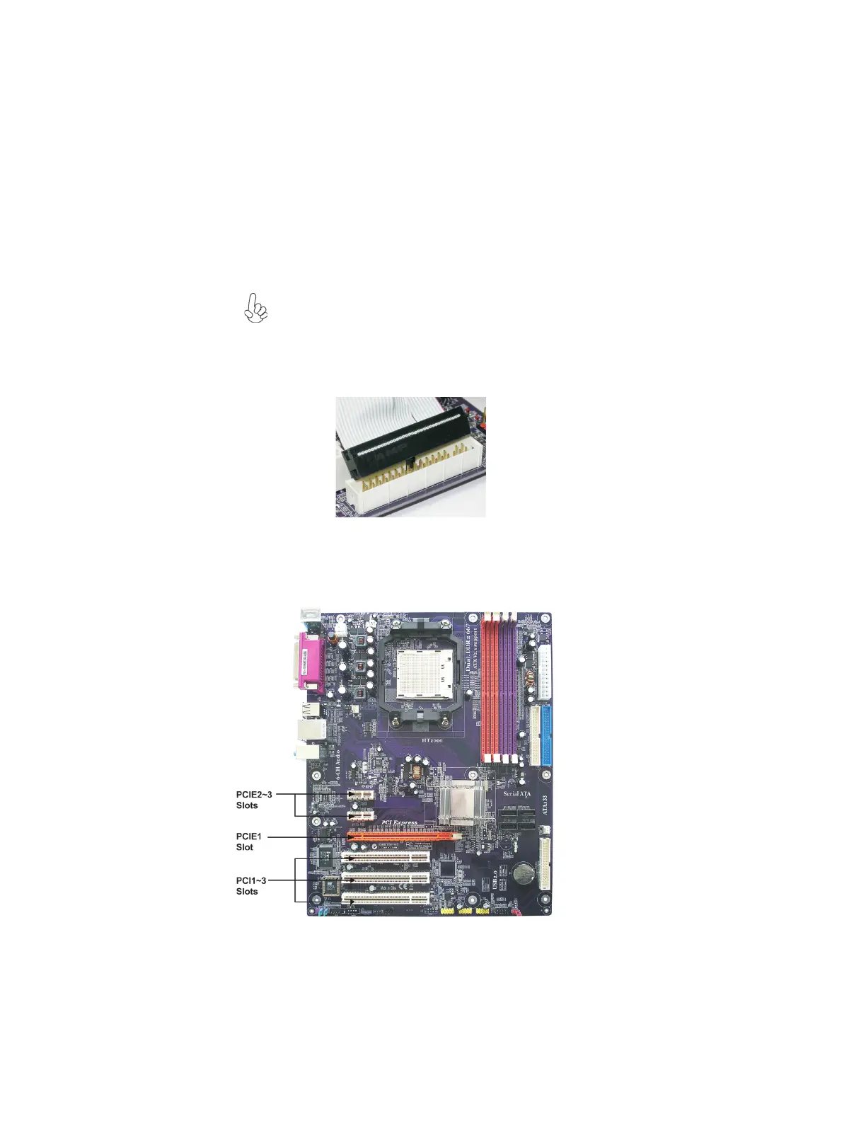
Installing Add-on Cards
The slots on this motherboard are designed to hold expansion cards and connect them to the
system bus. Expansion slots are a means of adding or enhancing the motherboard’s features
and capabilities. With these efficient facilities, you can increase the motherboard’s capabili-
ties by adding hardware that performs tasks that are not part of the basic system.
FDD1: Floppy Disk Connector
This connector supports the provided floppy drive ribbon cable. After connecting the single
end to the onboard floppy connector, connect the remaining plugs on the other end to the
floppy drives correspondingly.
Installing a Floppy Diskette Drive
The motherboard has a floppy diskette drive (FDD1) interface and ships with a diskette
drive ribbon cable that supports one or two floppy diskette drives. You can install a 5.25-
inch drive and a 3.5-inch drive with various capacities. The floppy diskette drive cable has
one type of connector for a 5.25-inch drive and another type of connector for a 3.5-inch
drive.
You must orient the cable connector so that the pin 1 (color) edge of the
cable corresponds to the pin 1 of the I/O port connector.