11
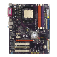
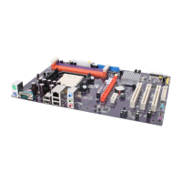
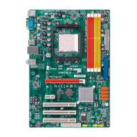
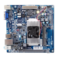
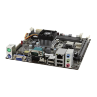
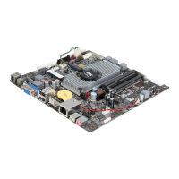
Installing the Motherboard
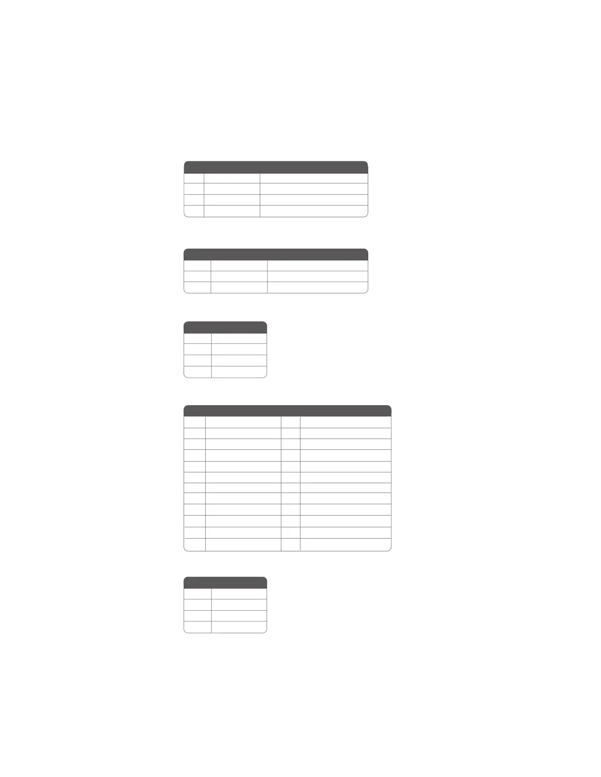
CPU_FAN1: CPU Cooling FAN Power Connector
PWR1: ATX 12V Power Connector
ATX1: ATX 24-pin Power Connector
1 +3.3V 13 +3.3V
2 +3.3V 14 -12V
3 Ground 15 COM
4 +5V 16 PS_ON
5 Ground 17 COM
6 +5V 18 COM
7 Ground 19 COM
8 PWRGD 20 -5V
9 +5VSB 21 +5V
10 +12V 22 +5V
11 +12V 23 +5V
12 +3.3V 24 COM
Pin Signal Name Pin Signal Name
SPK1: Internal speaker
CAS_FAN1/SYS_FAN1: Cooling FAN Power Connectors
1 GND System Ground
2 +12V Power +12V
3 Sense Sensor
Pin Signal Name Function
1 GND System Ground
2 +12V Power +12V
3 Sense Sensor
4 PWM CPU FAN control
Function
Pin Signal Name
4 +12V
3 +12V
2 Ground
1 Ground
Pin Signal Name
4 Signal
3 GND
2 Key
1 VCC
Pin Signal Name