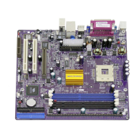
CPU_FAN1/SYSTEM_FAN: FAN Power Connectors
Pin Signal Name Function
1 GND System Ground
2 +12V Power +12V
3 Sense Sensor
SPK1: Internal speaker
Pin Signal Name
1 SPKR
2 NC
3 GND
4 +5V
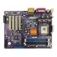
The Panel Connectors
PANEL1
If there is a headphone jack or a microphone jack on the front panel, connect
the cables to the PANEL1 on the mainboard.
Pin Signal Name Pin Signal Name
1 MIC IN 2 GND
3 VCCMIC 4 +5V AUDIO
5 LINE OUT (R) 6 LINE OUT (R)
7 NC 8 EMPTY
9 LINE OUT (L) 10 LINE OUT (L)
2 1
10 9
PANEL2
This panel connector provides a set of switch and LED connectors found on
ATX case. Refer to the table below for information.
Pin Signal Name Pin Signal Name
+1 HDD LED +2 SPD-LED Indicator
-3 HDD LED 4 SPD-LED Indicator
5 Reset Switch 6 POWER ON/OFF
7 Reset Switch 8 POWER ON/OFF
9 NC 10 EMPTY
HDD LED
(Pins 1, 3)
2 1
Reset Switc