Connecting Optional Devices
Refer to the following for information on connecting the mainboard’s optional
devices:
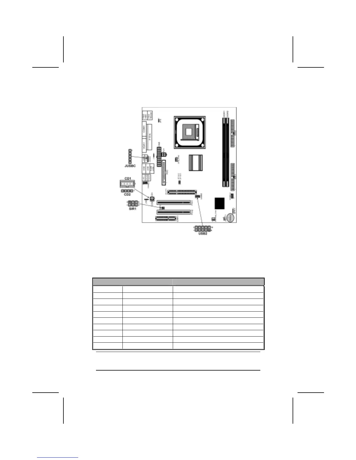
USB2: Front panel USB ports
The mainboard has USB ports installed on the rear edge I/O port array. Addi-
tionally, some computer cases have USB ports at the front of the case. If you
have this kind of case, use auxiliary USB connectors USB2 to connect the
front-mounted ports to the mainboard.
Pin Signal Name Function
1 VREG_FP_USBPWR0 Front Panel USB Power
2 VREG_FP_USBPWR0 Front Panel USB Power
3 USB_FP_P0- USB Port 0 Negative Signal
4 USB_FP_P1- USB Port 1 Negative Signal
5 USB_FP_P0+ USB Port 0 Positive Signal
6 USB_FP_P1+ USB Port 1 Positive Signal
7 GND Ground
8 GND Ground
9 KEY No pin
10 USB_FP_OC0 Overcurrent signal
Note: Please make sure that the USB cable has the same pin assignment as indi-
cated above. A different pin assignment may cause damage or system
hang-up.
17