10
Installing the Motherboard
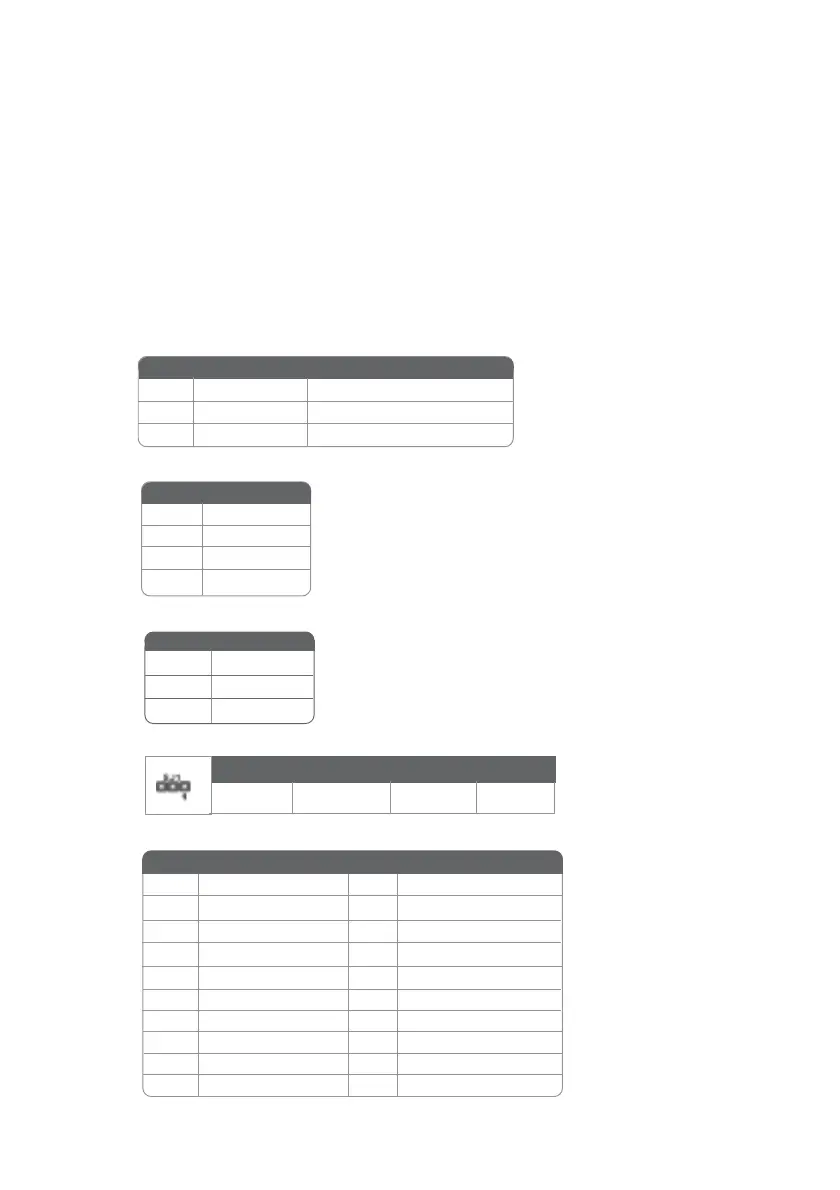
CPUFAN1/CASFAN1: FAN Power Connectors
Connecting Case Components
After you have installed the motherboard into a case, you can begin con-
necting the motherboard components. Refer to the following:
1 Connect the CPU cooling fan cable to CPUFAN1.
2 Connect the case cooling fan connector to CASFAN1.
3 Connect the case speaker cable to SPK1.
4 Connect the case switches and indicator LEDs to the PANEL1. If there are 3
pins in the case LED cable, connect to SJ1.
5 Connect the standard power supply connector to ATX1.
6 Connect the auxiliary case power supply connector to ATX2.
SJ1: Single-color LED header
ATX1: ATX 20-pin Power Connector
SPK1: Internal speaker
Pin Signal Name
1 VCC
2 Key
4 Signal
3 Ground
ACPI LED function
Pin Signal Name
1 ACPI LED
2 ACPI LED
3 5VSB
Pin Signal Name
1 GND System Ground
2
+12V Power +12V
3
Sense Sensor
Pin Signal Name Function
1 +3.3V 11 +3.3V
2 +3.3V 12 -12V
10 +12V 20 +5V
3 Ground 13 Ground
4 +5V 14 PS ON#
5 Ground 15 Ground
6 +5V 16 Ground
7 Ground 17 Ground
8 PWRGD 18 -5V
9 +5VSB 19 +5V
Pin Signal Name Pin Signal Name
Light Blinking Blinking Dark
S0 S1 S3 S4/S5