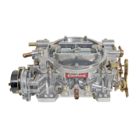
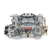
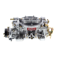
PERFORMER SERIES CARBURETOR
ELECTRIC CHOKE KIT
CATALOG NUMBER:#1478
For Edelbrock #1405 & #1407 carburetors
INSTALLATION INSTRUCTIONS
The enclosed electric choke kit is designed to replace the existing manual choke on Edelbrock Performer Series carburetors #1405 and #1407. Please fol-
low the instructions closely to ensure a proper installation. For technical questions call: 1-800-416-8628.
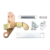
INSTALLATION KIT CONTENTS
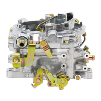
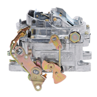
FIGURE 1
Brass
Plug
(Choke Vacuum Passage)
Choke Lever & Hex Head Screw
Airhorn
Screw
red wire (+)
to ignition key activated 12V source
Front of Carburetor
1- Choke Piston Housing
1- Connecting Rod
1- Thermostatic Coil Assembly w/Cap
1- Choke Cable Lever
1- Baffle Plate
1- Choke Piston Housing Seal
1- Choke Cap Gasket
1- Hair Clip Retainer
3- Choke Housing Attaching Screw
1- Choke Ground Wire (black)
3- Choke Cap Screw
1- Choke Positive Wire (red)
3- Choke Cap Retainer
1- Shaft Subassembly
1- 1/4”AN Washer
1- Lever (14-555)
CHOKE INSTALLATION
1. Remove the carburetor from the engine by disconnecting all linkages and lines.
Use the original carburetor Installation Instructions as a guide.
2. Remove the manual choke cable clamp bracket (Figure 1) by removing the airhorn screw. Re-tighten the airhorn screw after the bracket has been
removed.
Front of
carburetor
Manual Choke
Cable Clamp
Bracket
3. Remove the choke cable lever hex head screw and the choke cable lever (Figure 1).
4. Remove the screw A (Figure 3) that holds the choke linkage to the shaft subassembly.
5. Remove hair clip B and pull the shaft subassembly out of the airhorn.
6. Place the new lever #14-555 on the new shaft and slide this subassembly into the airhorn. The lever should be located on the shaft using Figure 7 as
a guide. Using the hair clip, reattach the fast idle linkage rod D.