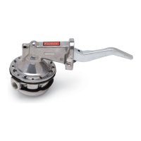
RACING FUEL PUMP
CATALOG #1711-Small-block Chevrolet
#1712-Big-block Chevrolet
#1715-Small-block Ford (289-351W)
INSTALLATION INSTRUCTIONS
• PLEASE study these instructions carefully before installing your new fuel pump . If you have any questions or problems, do not hesi-
tate to contact our Technical Hotline at: 1-800-416-8628.
• DESCRIPTION: Edelbrock Fuel Pumps are for racing applications such as drag racing, circle track racing or marine use where there
is a demand for high volume fuel delivery. These pumps are compatible with both gasoline and alcohol fuels. They have been
thoroughly tested and proven to have flow capacity significantly greater than other popular mechanical fuel pumps used for
competition.
• WARNING: Personal protection must be given careful consideration. The pump body itself is spring loaded with a heavy diaphragm
spring. If the unit is taken apart for adjustment or re-positioning of the lower pump body, extreme caution should be taken when
assembling and disassembling the upper pump body to and from the lower pump body. Upon installation of the fuel pump on the
engine, care should be taken to ensure that all fuel lines and fittings are properly installed, tight, and not leaking fuel.
IMPORTANT NOTES:
• Inlet and outlet ports are tapped to 1/2" NPT.
• For maximum fuel flow delivery Edelbrock #8122 (22") or #8127 (27") stainless steel braided fuel line is recommended.
• Fuel pressure can be controlled with Edelbrock Fuel Pressure Regulator Kits (#8190 for gasoline or #8194 for alcohol).
• Edelbrock repair kit #1799 is available for you to replace critical components of the pump when necessary.
• Edelbrock Universal Fuel Pump Kit #1798 is a machined aluminum plate that can be used to relocate the inlet and outlet fittings to the
bottom of the fuel pump for improved clearance in some engine compartments. Required for 1970-1/2 to 1981 Camaros as well as
many other applications.
• For off-road and race track applications we suggest the use of a shield between fuel pump and wheels to proven dirt from plugging
pump vent hole.
• Output fuel pressure is 13 to 14 psi. THE USE OF A SUITABLE FUEL PRESSURE REGULAR IS MANDATORY.
• INSTALLATION: Installation of the mechanical fuel pump is the same as for OEM pumps. If uncertain of the procedure to follow for
your particular vehicle, consult the appropriate repair manual for your model vehicle. Note that the fuel inlet and outlet of the
Edelbrock Racing Fuel Pump is much bigger than original equipment (1/2" NPT) and that a Universal Fuel Pump Adapter #1798 is
available if the larger physical size of the pump requires relocation of the inlet and outlet fittings. BE SURE THAT A SUITABLE
FUEL PRESSURE REGULATOR (Edelbrock #8190 or #8194) IS USED TO REDUCE THE PRESSURE TO THE CARBURETOR
AND PREVENT FLOODING.
NOTE: On some 351-W Ford engines there may be casting flash on the front cover which will interfere with proper seating of your
new fuel pump. File this area flat for proper gasket seating.
• RE-POSITIONING THE LOWER PUMP BODY: The lower pump body may be re-positioned as needed to allow better alignment
of the fittings for specific applications. Referring to the exploded view on the following page, remove ten allen head screws from the
perimeter of the pump pulsator cover and separate lower fuel pump body from upper fuel pump body. Rotate lower pump body to
desired new position and start but do not fully tighten the ten allen head retaining screws. Before fully tightening these screws, the
rocker arm must be actuated to and held in the “full stroke” position. This is done to ensure that the diaphragm will be pulled to and
held in its maximum working (flexed) position while the retaining screws are torqued tight (20-25 in/lbs.). This procedure will ensure
against premature diaphragm wear and subsequent failure due to over-stretching of the diaphragm material when in the full stroke posi-
tion. Another by-product of an improperly set diaphragm is erratic fuel flow and pressure.
The ten allen head retainer screws should then be torqued to their 20-25 in/lbs. specification in a criss-cross or “star” pattern, to ensure
even, progressive tightening. CAUTION: Do not overtorque these allen capscrews or serious pump diaphragm damage will occur.
This procedure can be assisted by holding the fuel pump in a vise or appropriate fixture, and holding the rocker arm down with a pipe
or similar tool.
After installing the fuel pump, run the engine and check for fuel leaks and proper operation. Correct as necessary.
©1998 Edelbrock Corp. Rev. 6/98