Quick Start Guide
– 2 –
3. Ground the Switch
Ensure the rack on which the switch is to be mounted is
properly grounded and in compliance with ETSI ETS 300 253.
Verify that there is a good electrical connection to the
grounding point on the rack (no paint or isolating surface
treatment).
Attach a lug (not provided) to a #12 AWG (PoE switch) or #18
AWG (non-PoE switch) minimum grounding wire (not
provided), and connect it to the grounding point on the
switch rear panel. Then connect the other end of the wire to
rack ground.
Caution
:
The earth connection must not be removed
unless all supply connections have been disconnected.
Caution:
The device must be installed in a restricted-access
location. It should have a separate protective earthing
terminal on the chassis that must be permanently
connected to earth to adequately ground the chassis and
protect the operator from electrical hazards.
4. Connect Power
a. Connect AC Power
Plug the AC power cord into the socket on the rear of the
switch.
Connect the other end of the power cord to an AC power
source. Verify that the external AC power requirements for
the switch can be met as listed below:
ECS2100-10T: AC 100-240 V, 50-60 Hz, 0.5 A
ECS2100-10P: AC 100-240 V, 50-60 Hz, 2.1 A
ECS2100-28T: AC 100-240 V, 50-60 Hz, 0.5 A
ECS2100-28P: AC 100-240 V, 50-60 Hz, 3.2 A
ECS2100-28PP: AC 100-240 V, 50-60 Hz, 5.8 A
ECS2100-52T: AC 100-240 V, 50/60 Hz,1 A
ECS2110-26T: AC 100-240 V, 50/60 Hz,1 A
Warning:
For the ECS2100-10P, the bottom of the
enclosure is a hot surface. Do not touch!
Note:
For International use, you may need to change the AC
line cord. You must use a line cord set that has been
approved for the socket type in your country.
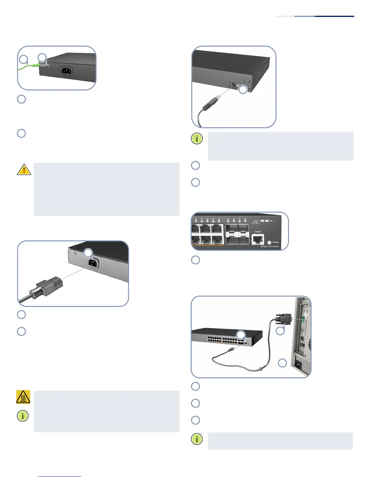
b. Connect DC power to ECS2100-10PE
Note:
The ECS2100-10PE includes an AC-DC power adapter.
Connect the AC-DC power adapter to the switch and to an
AC power source. The AC-DC adapter provides 54 VDC,
1.67 A of power to the switch.
Plug the DC power cable into the socket on the rear of the
switch.
Plug the AC-DC power adapter into a nearby AC power
outlet.
5. Verify Switch Operation
Verify basic switch operation by checking the system LEDs.
When operating normally, the Power and Diag LEDs should
be on green.
6. Perform Initial Configuration
Connect a PC to the switch console port using the included
console cable.
Configure the PC’s serial port: 115200 bps, 8 characters, no
parity, one stop bit, 8 data bits, and no flow control.
Log in to the CLI using default settings: Username “admin”
and password “admin.”
Note:
For further information on switch configuration, refer
to the Web Management Guide and CLI Reference Guide.