4-3
Twisted-Pair Devices
4
Network Wiring Connections
Today, the punch-down block is an integral part of many of the newer equipment
racks. It is actually part of the patch panel. Instructions for making connections in the
wiring closet with this type of equipment follows.
1. Attach one end of a patch cable to an available port on the switch, and the other
end to the patch panel.
2. If not already in place, attach one end of a cable segment to the back of the
patch panel where the punch-down block is located, and the other end to a
modular wall outlet.
3. Label the cables to simplify future troubleshooting. See “Cable Labeling and
Connection Records” on page 4-6.
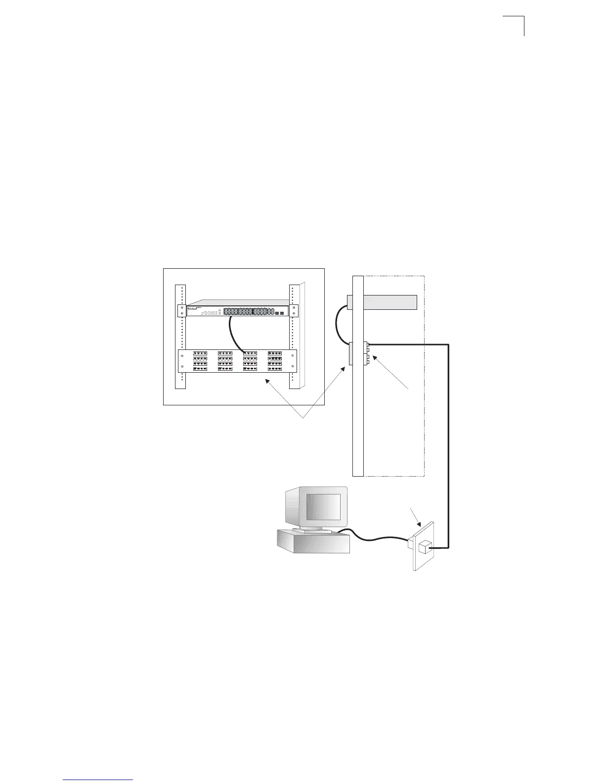
Figure 4-2 Network Wiring Connections
Equipment Rack
(side view)
Switch
Patch Panel
Punch-Down Block
Wall
25 27
26 28
27 28
 Loading...