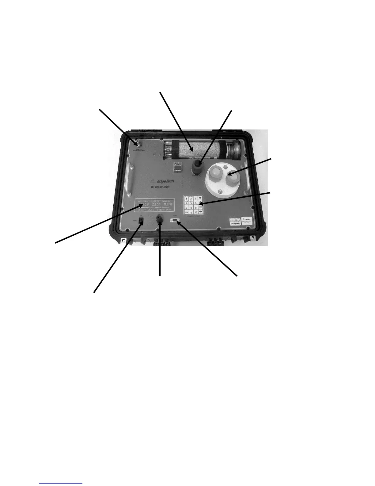
10.0 PANEL DESCRIPTION
2. AIR DRYER
1. AIR INLET 3. WATER FILL TUBE
4. TEST
CHAMBER
5. KEYPAD
9.
INFORMATION
DISPLAY
7. ANALOG OUTPUT 6. DIGITAL OUTPUT
8. ON/OFF SWITCH
Figure 10-1 RH-CAL Panel Description
1. Air Inlet (Sample In) – Brings in room air for use in the system. An
Instrument Air line may also be connected. (1/4 inch compression
fitting)
2. Air Dryer – Removes moisture from incoming air.
3. Water Fill Tube – Supplies water to the temperature controlled Saturator.