16
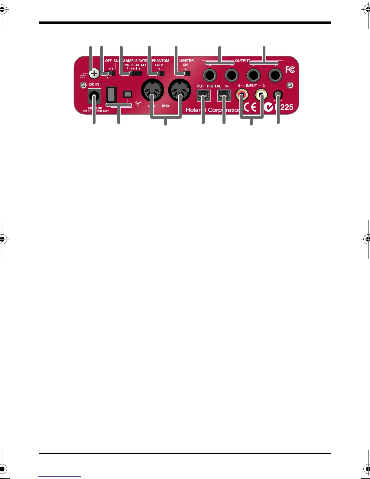
Front and rear panel
fig.rear.eps_60
19.
Phantom power switch
This is an on/off switch for the phantom power supplied to the XLR connectors of
the
combo input jacks (1)
on the front panel.
* You must leave the phantom power turned off (right position) unless condenser mics
requiring phantom power are connected to the XLR jacks. Supplying phantom power
to a dynamic mic or an audio playback device may cause malfunction. For details on
the requirements of your mic, refer to its owner’s manual.
(The FA-66’s phantom power supply: DC 48 V, 20 mA maximum)
20.
Limiter switch
This turns the FA-66’s hardware limiter on/off.
If a sudden, high-volume sound is input to the
combo input jacks (1)
, the limiter
applies mild compression to prevent clipping from occurring at the AD converter.
* Clipping noise will be heard if the input signal exceeds the capacity of the limiter.
21.
Output jacks 3, 4 (Nominal output: +4 dBu)
These jacks output analog audio signals. Balanced output is supported.
22.
Main output jacks (output jacks 1, 2) (Nominal output: +4 dBu)
These output the mixed sound that is being input via the input jacks and being
output from the computer. You can use the
output volume control (12)
to adjust
the volume.
23.
MIDI IN/OUT connectors
You can connect these to the MIDI connectors of your MIDI equipment to send and
receive MIDI messages.
24.
Digital output connector (optical)
Use this when you want to digitally connect an audio device, such as an MD or DAT
unit.
The signals sent from
OUTPUT 5
and
6
(if using WDM, EDIROL FA-66 OUT 3
➔
see p. 31) are output to the
digital output connector
.
20 21
14 15 18 19
22
16 24 25 2717 23 26
FA-66_e.book 16 ページ 2006年1月12日 木曜日 午前11時32分