Under the Terminal Cover
4-
The isolation between TB1 and TB2 is minimal. There is also minimal isolation
between TB3 and TB6. The isolation between these groups and line (neutral) and TB4
is 4kV.
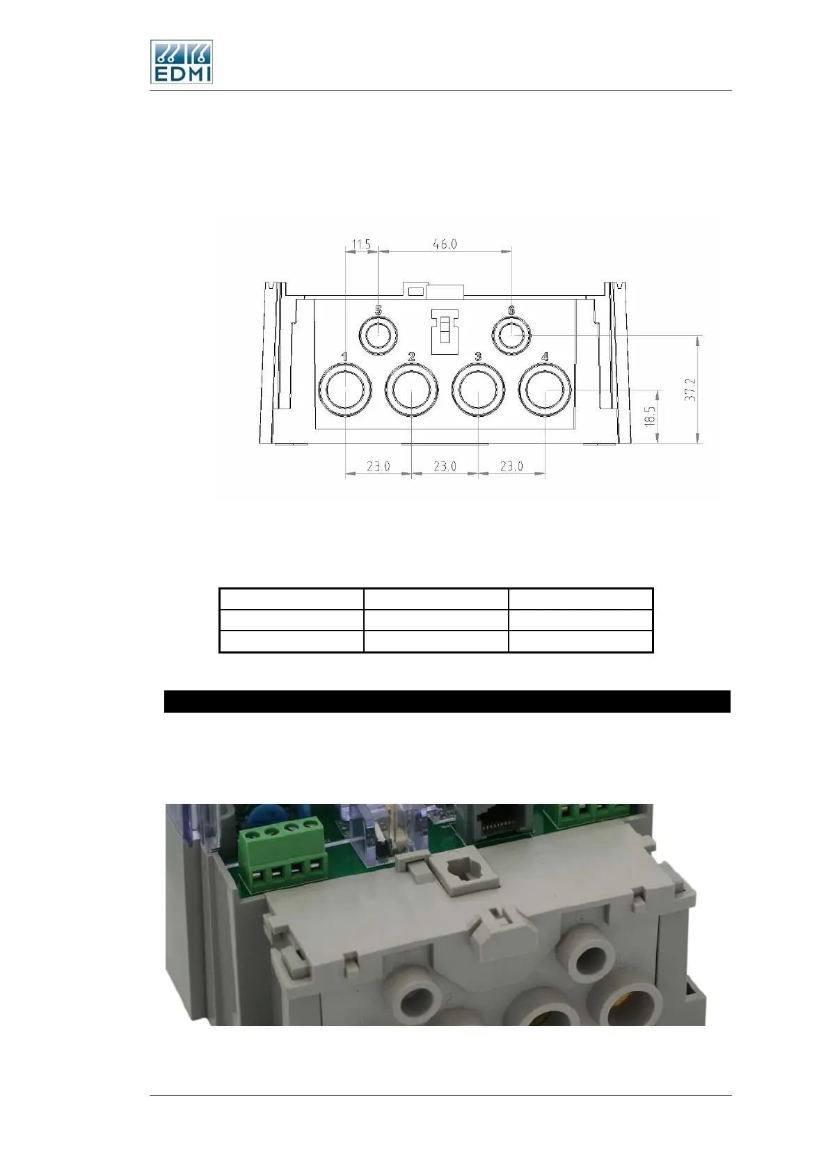
Figure 4-7 gives the terminal spacing of TB5.
• Figure 4-7 TB5 terminal spacings
Table 4-2 gives the terminal inner dimensions.
Terminal Profile Dimensions
Main Circuit Round 9.0 mm Ø
Load Circuit Round 5.3 mm Ø
• Table 4-2 Terminal sizes
Finger Guard
A finger guard may be fitted over the TB5 terminal screws. This can help prevent
accidental contact with the supply voltage, as well as allowing these connections to be
sealed.
• Figure 4-8 The finger guard in place
The Mk7A Meter 4-7
 Loading...
