5-
The sealable screws have 2.15mm diameter holes to accommodate standard sealing
wire. The two sealable screws at the top of the meter seal the internals of the meter.
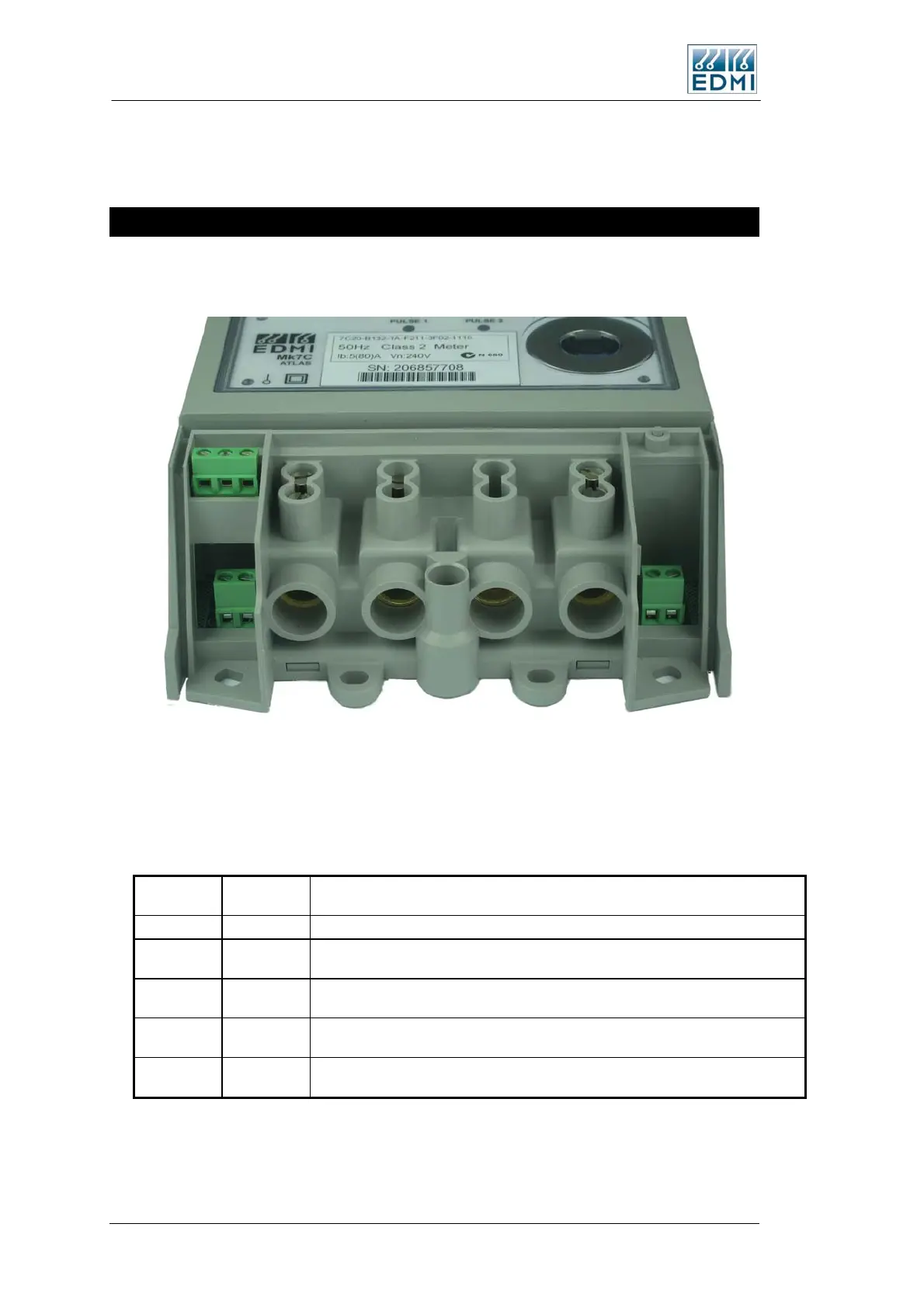
Under the Terminal Cover
Most of the connections to the meter occur under the terminal cover. Figure 5-8 shows
the terminals available on a PLC meter with 4 I/O.
TB3 TB4
TB2
TB1
• Figure 5-8 Under the terminal cover of the meter
The meter has several communications options, which affect the range of other options
available. The Order Code is the digit from the ‘Remote Communications’ section of
the Mk7C order codes.
Model
Order
Code
Description
Basic 0 No communications besides the optical port.
Passive 1,3,7
Passive RS232 / RS485 ports. This is a low power design which limits some
options such as relay outputs. It cannot have active inputs.
Active 2,5,6
Active RS232 / RS485 ports. This has a powerful isolated supply to run the
communication ports, and external GSM/GPRS modem, and active inputs.
Active Dual 9
2 Active RS232 ports. This has a powerful isolated supply to run the
communication ports, and external GSM/GPRS modem, and active inputs.
PLC A,C
PLC. This has an internal PLC communications interface, but no RS232 or
RS485 port.
• Table 5-1 Meter options
Figure 5-9 illustrates the terminal layout diagrammatically, and Figure 5-10 gives the
details of the terminal itself.
5-6 EDMI Atlas Hardware Reference Manual
 Loading...