Do you have a question about the EDMI Atlas Series and is the answer not in the manual?
Guidance on how to navigate and utilize the manual effectively.
Explains the symbols, formatting, and conventions used throughout the document.
Details the physical size and mounting instructions for the Mk10 meter.
Identifies and describes the visible components and indicators on the Mk10 meter.
Explains access and components found under the terminal cover of the Mk10 meter.
Describes how to remove and connect CT to VT links for testing purposes.
Explains the purpose and location of the configuration jumper for security.
Comprehensive guide to electrical connections, including current, voltage, and communication ports.
Wiring for current and voltage inputs on the Mk10 meter.
Lists and describes available serial port configurations (RS232, RS485, PLC).
Details on the RS-485 port configuration and operation.
Connection details for the FLAG and ANSI communication ports.
Details the functionality and specifications of the meter's input and output terminals.
Information on the internal, external, and UPS battery backup systems.
Specifics on the UPS battery's function and characteristics.
Explains the operation of the LCD display and control buttons.
Details the function and operation of the billing reset button.
Guidance on meter servicing and when to contact EDMI.
Details the physical size and mounting instructions for the Mk10D meter.
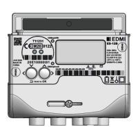
Identifies and describes the visible components of the Mk10D meter.
Explains access and components under the terminal cover for the Mk10D.
Describes the CT to VT links and their removal methods for testing.
Explains the purpose and location of the configuration jumper for the Mk10D.
Comprehensive guide to electrical connections for the Mk10D meter.
Wiring for current and voltage inputs on the Mk10D meter.
Lists available serial port configurations for the Mk10D.
Details on the RS-232 port configuration and functionality.
Details on the RS-485 port configuration.
Describes the functionality and types of inputs and outputs available.
Information on the internal battery used in the Mk10D meter.
Explains the LCD display and control button functionality for the Mk10D.
Details the operation of the Reconnect/Boost/Billing Reset button.
Details the physical size and mounting instructions for the Mk7A meter.
Identifies and describes the visible components on the Mk7A meter.
Explains access and components under the terminal cover for the Mk7A.
Explains how permanent VT to CT connections are handled on the Mk7A.
Explains the purpose and location of the configuration jumper for the Mk7A.
Comprehensive guide to electrical connections for the Mk7A meter.
Wiring diagrams and specifications for current and voltage inputs.
Details on the RS-232 serial port and its power output capabilities.
Describes the functionality and types of inputs and outputs available.
Information on internal and external battery options for the Mk7A.
Explains the LCD display and control button functionality for the Mk7A.
Details the operation of the Reconnect/Boost/Billing Reset button.
Details the physical size and mounting instructions for the Mk7C meter.
Identifies and describes the visible components on the Mk7C meter.
Explains access and components under the terminal cover for the Mk7C.
Explains the purpose and connection method for the configuration jumper.
Comprehensive guide to electrical connections for the Mk7C meter.
Details the passive and active RS-232 serial port configurations.
Details the passive and active RS-485 serial port configurations.
Describes the functionality and types of inputs and outputs available.
Information on the internal battery and LCD/Select button usage.
Instructions for fitting GSM/GPRS modems to the Mk7C meter.
Details the physical size and mounting instructions for the Mk10E meter.
Identifies and describes the visible components on the Mk10E meter.
Explains access and components under the terminal cover for the Mk10E.
Details the terminal cover and meter lid tamper detection switches.
Explains the purpose and location of the configuration jumper for the Mk10E.
Comprehensive guide to electrical connections for the Mk10E meter.
Wiring for current and voltage inputs on the Mk10E meter.
Lists available serial port configurations for the Mk10E.
Details on the RS-485 port configuration.
Describes the functionality and types of inputs and outputs available.
Information on batteries and the super capacitor for power backup.
Explains the LCD display and control button functionality for the Mk10E.
Details the function of the Reconnect/Boost/Billing Reset button.
Guidance on meter servicing for the Mk10E.
Describes the different LCD display types and their features across meter models.
Explains how to navigate and use the LCD display and select button.
Details the concept of display sets and how to change them.
Describes the layout and meaning of elements shown on the LCD screen.
Lists the electrical quantities the meter can measure and calculation methods.
Specifies environmental and operational limits for meter performance.
Explains the graphical representation of energy flow directions.
Describes how energy terms are named and configured in the software.
| Type | Electricity Meter |
|---|---|
| Display | LCD |
| Phase | Single Phase, Three Phase |
| Communication | RS-485 |
| Mounting | DIN Rail |
| Operating Temperature | -25°C to +60°C |
| Storage Temperature | -40°C to +70°C |