Connections in Detail
6-
Connections in Detail
Current and Voltage
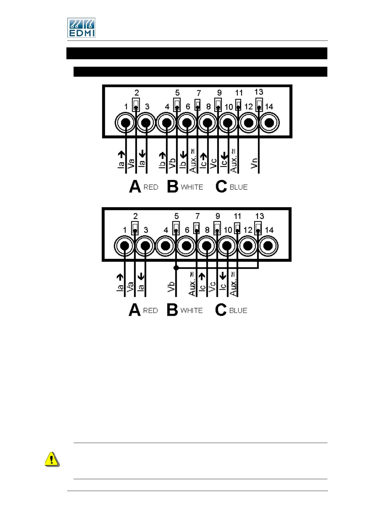
• Figure 6-14 TB1 CT and VT connections for 3 element (top) and 2 element
(bottom).
Figure 6-14 shows the two possible connection methods in either 2 (3 wire) or 3 (4 wire)
element mode. No internal modification to the meter is required to make it measure in 2
element (3 wire) or 3 element (4 wire) mode. For proper accuracy (especially when
measuring VA in 2 element mode) the measurement method must be set to 2 element
using EziView (see the External Transformers chapter in the Atlas Software Reference
Manual.). The connection to terminal 5 is not required in two element mode. Terminals
12 & 14 are not fitted in CT connected meters.
The nominal voltage input range dependant on the model number of the meter. The
current range depends on the current range of the meter, and should be limited to Imax.
In 3 element mode (4 wire) the maximum line to neutral voltage is 290V and the
maximum line to line voltage is 500V. When in 2 element (3 wire) configuration the
maximum line to line voltage is 290V. At any higher voltage the meter will not operate
correctly and damage may occur.
The Mk10E Meter 6-9

 Loading...