5-1
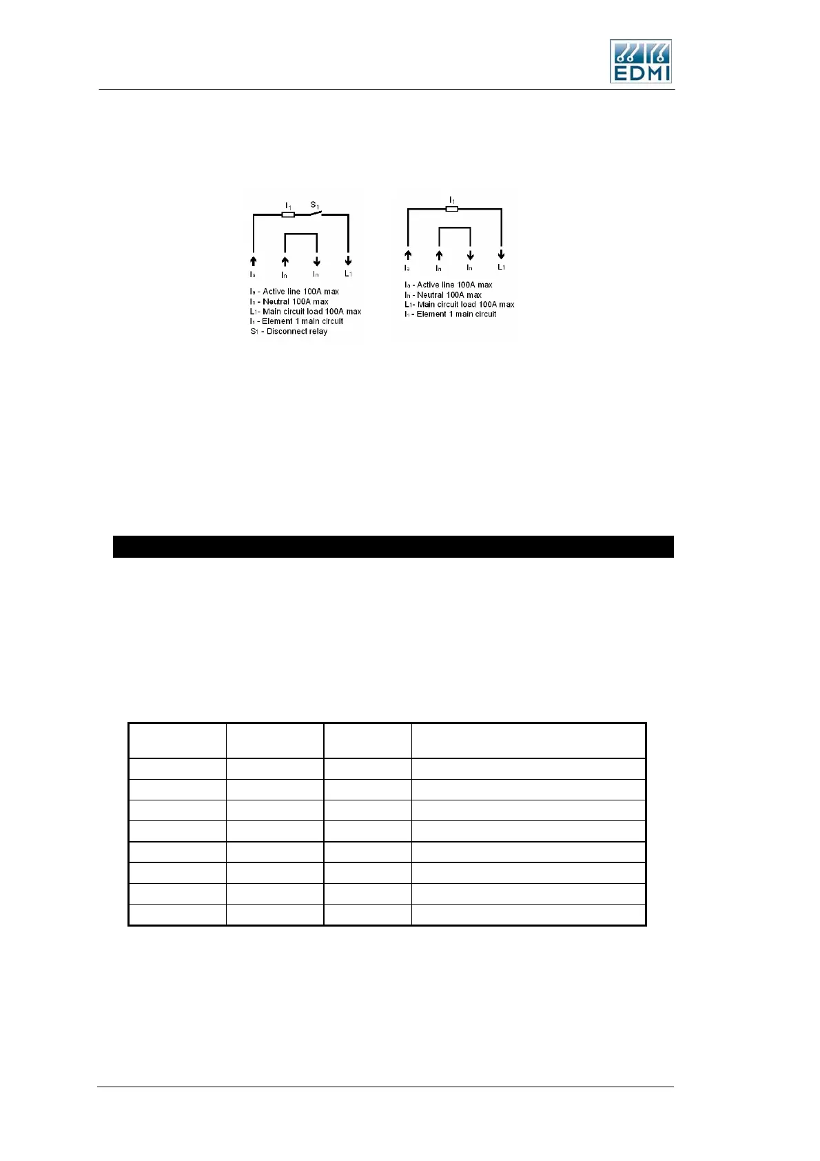
The meter may be fitted with an internal 100A disconnect relay, which interrupts the
active connection. Figure 5-15 illustrates the disconnect and non-disconnect options.
• Figure 5-15 Internal connection options
While the meter only has 1 measurement element for voltage, the meter has up to 2
measurement elements for current. The primary element I
1
is referred to as Main. The
other (optional) element measures the Neutral Current, and is referred to as Neutral.
Total is the same as Main. The Mk7C does not have a Load circuit like the Mk7A has.
To compare with the Mk10, Main is Phase A and Neutral is Phase C. While Total in the
Mk10 is the sum of all three phases, Total in the Mk7C is the Main element only.
RS-232 Passive
The RS-232 port on the meter uses an RJ45 connector, which complies with the RS-
232D standard. To connect to a modem, use a modem with an RJ45 connector or use an
RJ45 to DB9 adapter.
Meters fitted with a passive serial port derive power from the signal lines of the modem.
Thus the port cannot power an external modem. See Table 5-8 for connection details.
Pin 1 of the RJ45 is furthest on the right hand side.
RS232D RJ45
From Meter
RS232C DB9
To Modem
Description Full Name
TB4-1
TB4-2 1 CD Carrier Detect (to meter)
TB4-3
TB4-4 5 GND Ground
TB4-5 2 RX Receive Data (to meter)
TB4-6 3 TX Transmit Data (from meter)
TB4-7 7 CTS Clear to Send (to meter)
TB4-8 8 RTS Ready to Send (from meter)
• Table 5-8 RS-232 connections
The RTS and CTS hardware handshaking lines are looped back within the meter, but
they are not driven or detected by the meter. The meter draws power from the CD
and/or CTS lines, so a least one of these lines should be always driven high by the
modem. The meter does not sense the state of the CD line.
5-12 EDMI Atlas Hardware Reference Manual

 Loading...