EasyManuals Logo

EDMI Atlas Series User Manual

EDMI Atlas Series
112 pages
To Next Page IconTo Next Page
To Previous Page IconTo Previous Page
Page #52 background imageLoading...
Page #52 background image
4-
4
External Features
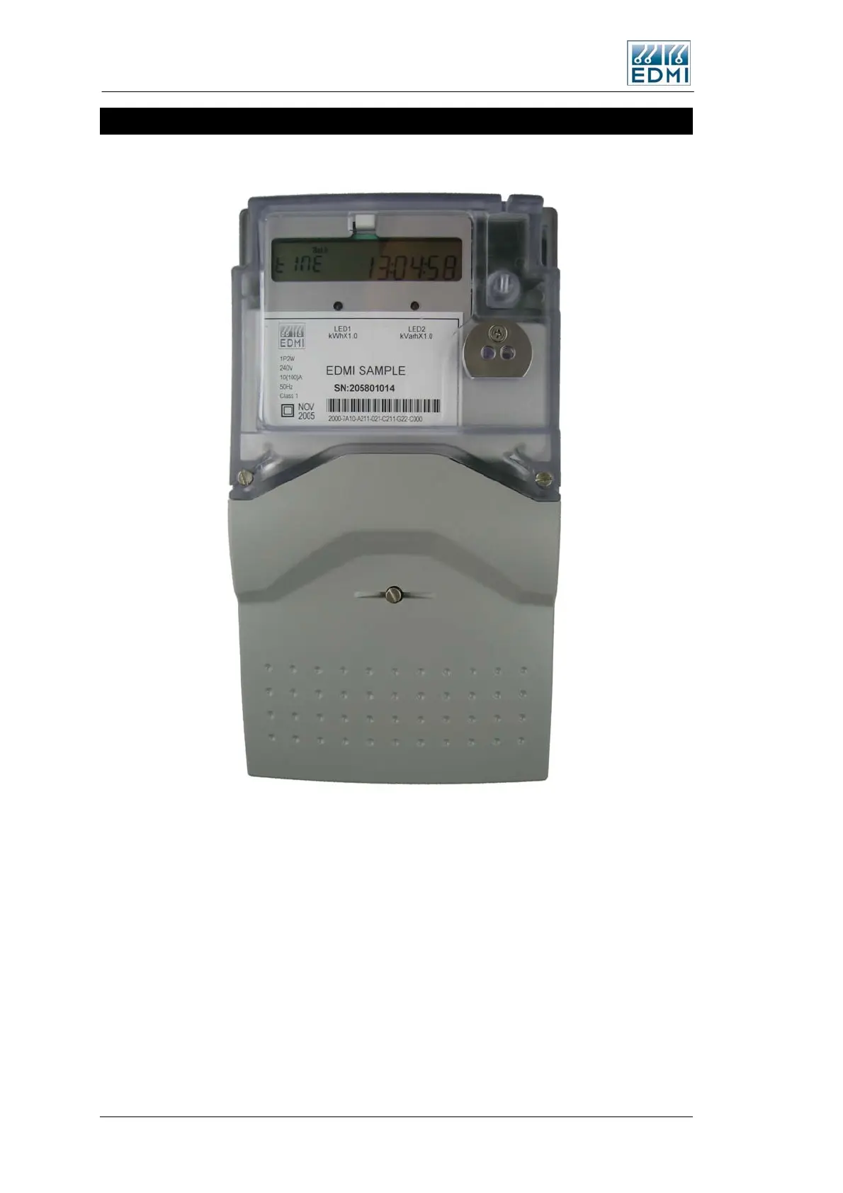
Figure 4-4 shows a view of the front of the meter (the specifics of your label will vary).
Figure 4-4 Front view of the meter with terminal cover fitted
The major parts visible in Figure 4-4 include:
The LCD display.
A Select button for cycling the display (push button just above the optical port).
Two pulsing LEDs for energy indication (PO3 and PO4).
A FLAG or ANSI port for local connection.
There is space for an optional Connect, Boost or Billing Reset button above the select
button (See page 4-14).
4-4 EDMI Atlas Hardware Reference Manual

Table of Contents

Questions and Answers:

Question and Answer IconNeed help?

Do you have a question about the EDMI Atlas Series and is the answer not in the manual?

EDMI Atlas Series Specifications

General IconGeneral
TypeElectricity Meter
DisplayLCD
PhaseSingle Phase, Three Phase
CommunicationRS-485
MountingDIN Rail
Operating Temperature-25°C to +60°C
Storage Temperature-40°C to +70°C

Related product manuals