3-1
RS-485
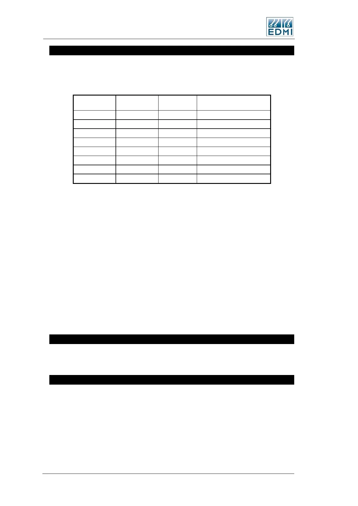
The RS-485 port on the meter has the factory option of either an RJ45, or a 5 way
terminal block. Table 3-4 lists the connections. Pin 1 of the RJ45 is on the right hand
side. Pin 1 of the terminal block is on the left hand side.
RJ45
Terminal
Block
Description Full Name
TB10-1 TX2 Transmit Data-SCADA port
TB10-2 RX2 Receive Data-SCADA port
TB10-3 1 TX+ (A) Transmit +
TB10-4 5 GND Ground
TB10-5* +5 +5V,140mA output
TB10-6 2 TX- (B) Transmit Data
TB10-7 4 RX- (B) Receive -
TB10-8 3 RX+ (A) Receive +
• Table 3-4 RS-485 connections
*TB10-5 is connected to a +7V power source from the meter.
To operate the meter in two wire mode, simply wire TX- to RX- and TX+ to RX+.
These may be wired together as a factory fitted option.
Note that the 5-pin terminal block has a different pinout to the EDMI mk6 and mk3
meter RS485 ports.
See Figure 3-4 and Figure 3-5 for the location of the connector. The 5 way terminal
block is fitted in the same place (instead of) the RJ45 shown.
RX2 and TX2 are only present if the port is a dual RS485/RS232 port, and in this case
RX2 and TX2 are RS232 signals.
One fitment option is two RJ45’s wired in parallel (TB9 and TB10) – this is useful for
wiring a series of meters together using premade cables.
PLC
In a PLC meter communications are made via the power line, coupled to Phase A and
Neutral.
FLAG Port
The meter can have either a Flag Port or an ANSI Port. Use a standard FLAG (IEC1107
physical standard) read head to connect the meter to a PC.
Note that it has occasionally been found that some FLAG heads need to be rotated 180
degrees for them to work. If you have problems try this.
3-12 EDMI Atlas Hardware Reference Manual

 Loading...