1. External electrical supply
2. Electrical supply connector
3. Earth (ground)
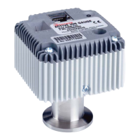
4. AIM active gauge
5. Active gauge connector
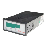
6. Logic interface connector
7. Vent-valve control (normally open)
1
8. TMP Fail (normally closed)
9. TMP Normal output (normally open)
1
10.Remote indicator equipment
11.Air-cooler
12.Vent-valve
13.External Standby switch
14.External Start/Stop switch
15.Speed/power indicator
1
These are solid-state switches in the Controller
A. Vacuum and control system
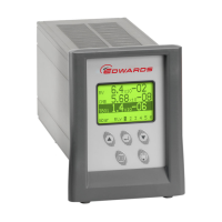
B. EXC Controller
L Live electrical supply
N Neutral electrical supply
E Earth (ground) electrical supply