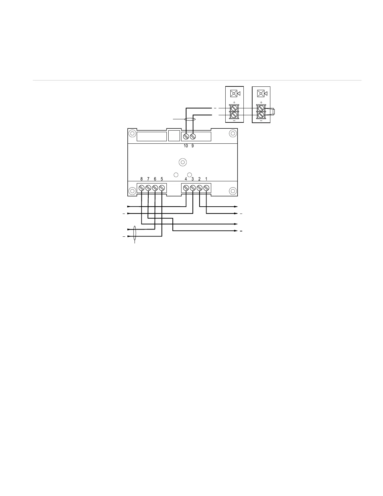
To wire the module:
1. Verify that all field wiring is free of opens, shorts, and
ground faults.
2. Make all the connections as shown in Figure 3 through
Figure 5.
Figure 3: Wiring diagram for NAC (personality code 5)
(1) Signal polarity is shown when the circuit is in supervisory state.
Polarity reverses when the circuit is active.
Supervised.
Power-limited unless connected to a nonpower-limited source. If
the source is nonpower-limited, eliminate the power-limited mark
and maintain a minimum of 0.25 in.
(6.4 mm) space from power-limited wiring. For other mounting
methods, see enclosure and bracket installation sheets to
maintain separation of power-limited and nonpower-limited
wiring. The wire size must be capable of handling fault current
from nonpower-limited source.
— or —
Use type FPL, FPLR, FPLP, or permitted substitute cables,
provided these power-limited cable conductors extending beyond
the jacket are separated by a minimum of 0.25 in. (6.4 mm)
space or by a nonconductive sleeve or nonconductive barrier
from all other conductors. Refer to the NFPA 70 National
Electrical Code for more details.
(4) If using a G1-P Genesis series horn while connected to a
compatible fire alarm control panel, a CDR-3 Bell Coder must
be used to comply with ANSI S3.41.
(5) 47 kΩ EOLR.
(6) Signaling line circuit (SLC) to next device.
(7) AUX riser (to next module or riser supervisory device).
(8) Power-limited regulated, power supply UL/ULC Listed for fire
protective signaling systems.
(9) AUX riser (from previous device).
(10) Signaling line circuit (SLC) from previous device. Supervised
and power-limited.
(6)
++
(7)
+
+
(1)(2)(3)(4)
(3)(8)
(9)
(10)
+
(5)
P/N P-047550-1802-EN • REV 04 • ISS 23JUN15 3 / 6