2 / 3 P/N 3102697-EN • REV 001 • ISS 24AUG20
Application
For Class A pathways, install SIGA-IM2 modules to segment the SLC
as required (e.g., by zone or by number of devices) to prevent a wire-
to-wire short from taking down the entire circuit. See Figure 3 and
Figure 4.
For Class X pathways (see Figure 5):
• Install a SIGA-IM2 module on the Class B out and Class A return
wiring inside the control unit, or in the same room, within 20 ft.
(6.1 m), and wiring enclosed in conduit or equivalently protected
against mechanical injury.
• Install a SIGA-IM2 module on both sides of one or more standard
mount modules contained in a common enclosure.
• Install a SIGA-IM2 module on both sides of a single standard
mount module, in the same room, within 20 ft. (6.1 m), and wiring
enclosed in conduit or equivalently protected against mechanical
injury.
• Install a SIGA-IM2 module on both sides of a common enclosure
containing one or more UIO plug-in modules, in the same room,
within 20 ft. (6.1 m), and wiring enclosed in conduit or equivalently
protected against mechanical injury.
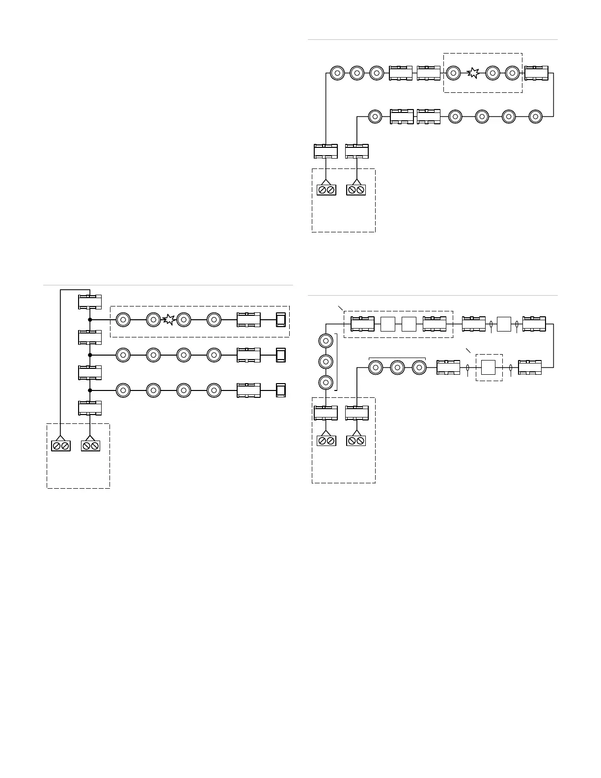
Figure 3: Typical Class A with isolated Class B branches
(1) Non-isolated devices effectively removed from the circuit
(2) Short circuit
(3) SLC Class B out
(4) SLC Class A return
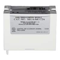
Figure 4: Typical Class A with isolators
(1) Non-isolated devices effectively removed from the circuit
(2) Short circuit
(3) SLC Class B out
(4) SLC Class A return
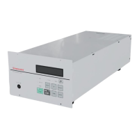
Figure 5: Typical Class X
(1) Common enclosure
(2) Standard mount module
(3) UIO plug-in module
(4) Field wiring in the same room, within 20 ft. (6.1 m), and enclosed
in conduit or equivalently protected against mechanical injury
(5) Automatic fire detectors attached to isolator bases
(6) SLC Class B out
(7) SLC Class A return
SLC
A+ A-
SLC
B+ B-
(1)
(2)
(3) (4)
FACU
IM2
IM2
IM2
IM2
SLC
A+ A-
SLC
B+ B-
(1
(2)
(3) (4)
FACU
IM2
IM2
IM2
IM2
SLC
A+ A-
SLC
B+ B-
(6) (7)
FACU
IM2
IM2
(2)
(4)
(2)
(4)
(4) (4)
(3)
(1)
(1)
(5)
(5)
(2)
IM2 IM2
IM2 IM2IM2
IM2IM2 IM2