A730-01-880 Issue E
Page 18 © Edwards Limited 2007. All rights reserved.
Edwards and the Edwards logo are trademarks of Edwards Limited.
Operation
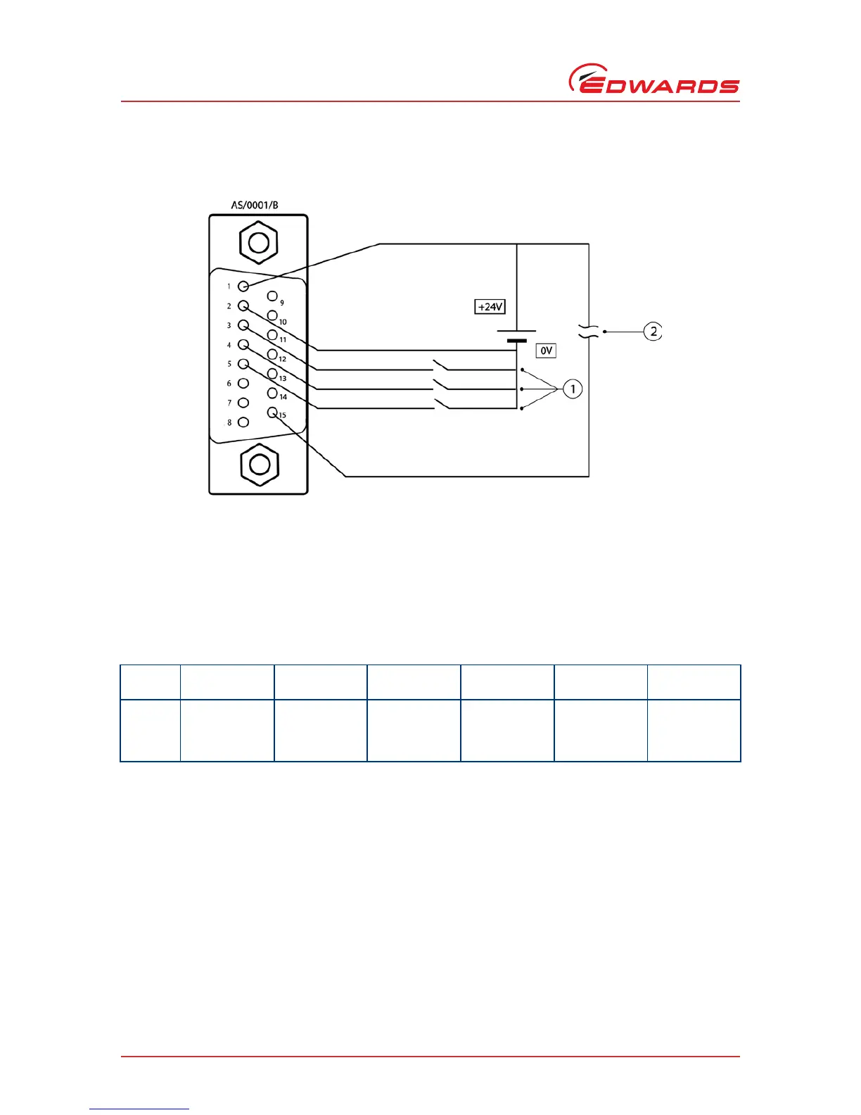
Figure 4 - Logic interface schematic
The tolerance of the power supply can be ±10%. Make sure all the unused pins are not connected.
Table 8 - Pin status on the logic interface connector
Mode
Speed
percentage
Pumping speed
(m
3
h
-1
)
Pin 1Pin 3Pin 4Pin 5
Normal 100% 35 24 V Link open open
Boost 116% 41 24 V Link Link Link
Idle 67% 23 24 V Link Link open
1. Speed control pins 3, 4 and 5
Maximum current per pin = 7 mA when linked to pin 1 (24 V)
2. Pump healthy signal
Signal high = normal (maximum permissible current = 100 mA)