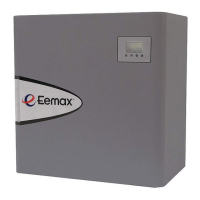
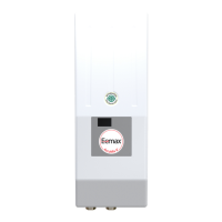
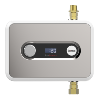
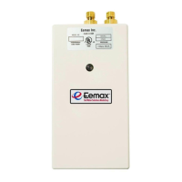
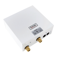
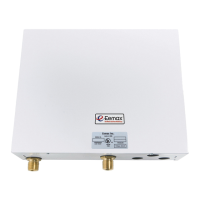
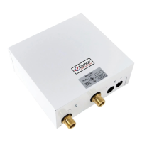
4) COMMISSIONING THE HEATER
BEFORE SWITCHING THE ELECTRICAL BREAKER “ON”, MAKE SURE
THE INLET AND OUTLET BALL VALVES ARE FULLY OPEN AND WATER
IS FLOWING THROUGH ALL POINTS OF USE FOR A MINUTE OR TWO
UNTIL THE FLOW IS CONTINUOUS AND FREE FROM AIR POCKETS.
DO NOT SWITCH THE BREAKER “ON” IF THERE IS ANY POSSIBILITY
THE WATER IN THE HEATER IS FROZEN.
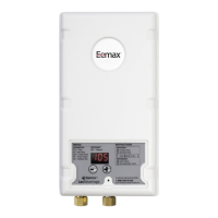
After verifying the heater has been
purged of air (see above) turn the circuit
breaker/disconnect “ON” and observe
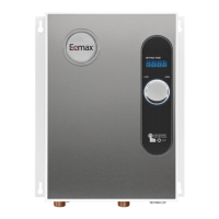
the start-up sequence on the display.
The LCD screen will display the SETPOINT
TEMPERATURE in degrees F.
Below the display are 4 push buttons that
are used to control the function of the
heater. Press the UP or DOWN buttons to
establish your desired temperature. Refer
to the CONTROL FEATURES section of this
manual for additional information.
The heater is fully installed and ready for use.
VOLTS AMPS RECOMMENDED
MODEL 3-PHASE DELTA Kw PER PHASE WIRE SIZE (CU) 90° C
AP032208 208 32 89 1 AWG
AP036208 208 36 100 1 AWG
AP041208 208 41 114 1 AWG
AP054208 208 54 150 2/0
AP064208 208 64 178 3/0
AP036480 480 36 44 8 AWG
AP039480 480 39 47 8 AWG
AP048480 480 48 58 6 AWG
AP054480 480 54 65 4 AWG
AP063480 480 63 76 3 AWG
AP072480 480 72 86 3 AWG
AP096480 480 96 116 1 AWG
AP108480 480 108 130 1/0
AP126480 480 126 152 2/0
AP144480 480 144 173 3/0
AP130600 600 130 130 1 AWG
AP150600 600 150 144 1/0
8
SETPOINT
TEMP120F