Do you have a question about the EemaX EX190 TC and is the answer not in the manual?
Covers essential safety points including independent circuits, grounding, proper installation, voltage, and electrical shock prevention.
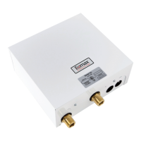
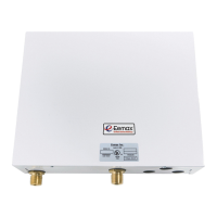
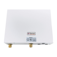
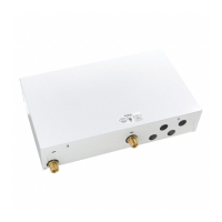
Unit must be mounted vertically with fittings at the bottom and a minimum of 8" clearance above.
Specifies cold water inlet on the right and hot water outlet on the left; reversal is not permitted.
Advises checking local codes for PTRV requirements and proper installation location if needed.
Details the use of supplied 3/4" NPT fittings and prohibits pipe dope or soldering to the inlet/outlet.
Emphasizes clearing pipes of debris before connection and flushing the system to prevent flow switch damage.
Instructs on installing isolating valves and performing thorough leak tests before electrical hook-up.
Mandates independent circuits with correctly rated double pole (208/240V) or single pole (277V) breakers.
Guides on connecting live wires to L1/L2, ground to GND, and stresses the critical importance of proper grounding.
Details opening hot water outlets to purge air and pressurize the system before energizing the heater.
Outlines procedures for 'T' models, including power indicator light behavior and temperature adjustment.
Explains how to adjust temperature via screws and manage flow rate for optimal performance with mixer faucets.
Addresses issues like no electric supply, low water flow, reversed connections, burned-out elements, and tripped ECO.
Covers high water flow, incorrect power supply, burned-out elements, and thermostat adjustment issues.
Lists part numbers for replacement heater core assemblies and relays based on model and voltage.
Identifies specific wire connectors (EX 100G, EX 284) used with the control board and modules.
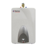
The Eemax "Series-Two" Water Heater is an electric instantaneous water heater designed for domestic use. This manual provides comprehensive installation and owner's instructions, emphasizing safety, proper installation, and maintenance to ensure optimal performance and energy savings.
The Eemax "Series-Two" heater is designed to take cold water and heat it to temperatures suitable for normal domestic usage, up to a maximum of 140°F (60°C). It operates on an instantaneous heating principle, meaning it heats water on demand rather than storing it in a tank. This design contributes to energy efficiency by eliminating standby heat loss. The unit utilizes two independent heating modules, each with its own circuit, to achieve the desired water temperature. The heater is equipped with a thermostatic control that modulates power to maintain a consistent water temperature once set.
The unit is designed for ease of use and integration into a domestic plumbing system. It features 3/4" NPT pipe connections for both cold water inlet and hot water outlet, which are clearly designated to prevent incorrect installation. For optimal performance and energy savings, the heater should be mounted as close as possible to the point of use, such as directly beneath a sink. It must be installed in a vertical position with the water fittings at the bottom to prevent element burnout and permanent damage.
The commissioning process involves ensuring the hot water circuit is free of air pockets before energizing the unit. This is achieved by opening all hot water outlets one at a time until water flow is continuous and free from air. The outlet ball valve is then used to gradually reduce water flow until the power indicator light on the second unit begins to pulsate, indicating the desired temperature (approximately 140°F) has been reached. For models with temperature adjustment screws, users can fine-tune the temperature by turning these screws counter-clockwise in small increments. Increasing water flow above the rate at which thermostatic control is effective will reduce the water temperature.
For single-lever mixer faucets, it is recommended to restrict the cold water supply to the faucet to match the flow rate of the hot water from the Eemax heater, which can be done by partially closing the cold water valve under the sink. This helps achieve better control over the mixed water temperature.
The manual highlights several maintenance-related aspects, primarily focused on troubleshooting and part replacement.
Troubleshooting: The manual provides a detailed troubleshooting guide for common issues.
Parts Replacement: The manual includes a diagram of replacement parts, such as the heater core assembly, ECO (push to reset), control board, and relay. This information is crucial for identifying and ordering the correct components if a repair is needed. Users are advised to contact Eemax technical service for assistance with installation or performance issues, and to have the serial number, model number, and installation date ready when calling.
Safety Warnings: The manual places a strong emphasis on safety. It warns against improper installation, adjustment, alteration, service, or maintenance, as these can lead to death, serious bodily injury, or property damage. Users are instructed to read the entire manual before installation or operation. Crucially, the electrical supply to the water heater must always be turned "OFF" at the main circuit breaker panel before removing the cover or servicing the unit to prevent electrical shock. Failure to ground the system properly is also highlighted as a severe hazard. The unit requires two dedicated independent circuits with correctly rated wires and circuit breakers. It is also critical to use the correct voltage type as specified on the rating plate, as using an incorrect voltage can cause significant problems. The use of pipe dope is prohibited, and soldering pipes while connected to the heater will cause serious damage.
| Power | 19 kW |
|---|---|
| Voltage | 380-415 V 3~ |
| Water Connection | 1/2 inch |
| Frequency | 50/60 Hz |
| Safety Features | Overheat protection |