Do you have a question about the EemaX EX320T3 and is the answer not in the manual?
This document describes the Eemax Three Phase Thermostatic Electric Instantaneous Water Heater, designed for commercial applications requiring hot water at temperatures up to 180°F (82°C). This guide provides comprehensive instructions for installation, operation, and troubleshooting, emphasizing safety and optimal performance.
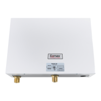
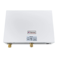
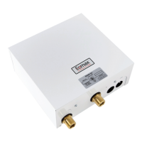
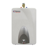
The Eemax Three Phase Thermostatic Electric Instantaneous Water Heater is engineered to provide on-demand hot water for various commercial needs, including washing, sluicing, and processing. Unlike traditional tank-style water heaters, this instantaneous unit heats water as it flows through, eliminating the need for a storage tank and providing a continuous supply of hot water. It is specifically designed to handle cold or pre-heated incoming water and raise its temperature to the desired level. The "thermostatic" aspect indicates its ability to maintain a consistent output temperature, which is crucial for many commercial processes. The unit operates on a three-phase electrical supply, making it suitable for industrial and commercial environments where such power is readily available. Its design incorporates individual electronic flow switches within each of the three heating modules, which activate the heating elements only when water is flowing, contributing to energy efficiency. The unit's ability to deliver hot water up to 180°F (82°C) makes it versatile for applications requiring high temperatures for sanitation or specific process requirements.
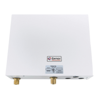
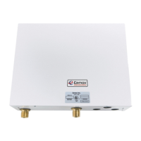
To ensure optimal performance and energy savings, the Eemax water heater should be installed as close as possible to the point of use. This minimizes heat loss in the piping and ensures that hot water is delivered quickly. The unit must be mounted in a vertical position with the water inlet and outlet located at the bottom. The cold water inlet is on the right-hand side, and the hot water outlet is on the left-hand side; these connections cannot be reversed. A minimum of 8 inches of space above the unit is required to facilitate easy replacement of the heating elements. The heater is fixed to the wall using screws through the four mounting holes on the backplate.
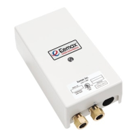
Proper plumbing is critical for the unit's operation. The heater is supplied with compression fittings for direct coupling to standard 1/2-inch (5/8-inch outside diameter) copper or plastic piping. It is essential to use these compression fittings and avoid tapered threaded pipe fittings or soldering pipes directly to the inlet or outlet, as excessive heat from soldering can damage the electronic flow switches. Isolating valves (full-flow ball valve type) should be installed on both the inlet and outlet pipes to allow the unit to be isolated for maintenance. Before connecting the heater, the supply pipes must be flushed to remove any debris that could damage the flow switches. After plumbing is complete, the system must be thoroughly checked for leaks. All hot water outlets fed by the heater should be opened one at a time for a minute or two to ensure continuous water flow, free from "gulping" and visible air pockets, which indicates that the system is purged of air.
Electrically, the unit requires its own independent circuit with five wires: three live, one neutral, and one ground, protected by a correctly rated four-pole breaker. It is crucial to verify the voltage rating on the unit's front plate and ensure it matches the electrical supply, as using an incorrect voltage can lead to severe damage or injury. The unit must not be connected in a delta configuration and must be properly grounded to prevent electrical shock. Before switching on the power at the main circuit breaker panel, it is imperative to ensure the hot water circuit is free of air pockets, as trapped air can cause premature failure of the heating elements. This is achieved by opening all hot water faucets until water flows continuously and smoothly.
Commissioning the heater involves several steps. With the inlet and outlet ball valves fully open, a hot water outlet should be turned on for one minute. Then, the electric supply at the circuit breaker panel can be switched on. The power indicator light will initially pulse and then stay full on after about 40 seconds, indicating the heater is operating at full power. The desired hot water temperature is achieved by slowly reducing the water flow using the outlet ball valve; lower flow rates result in higher temperatures and vice versa. The temperature adjustment screw on each module allows for fine-tuning the temperature. Turning the screw counter-clockwise in small increments and waiting 10-15 seconds to observe the indicator light pulsing regularly confirms that the thermostat has stabilized at the set temperature. This process should be repeated for all three modules to ensure all elements are pulsing equally and maintaining the desired temperature. The power indicator light should only be on when water is flowing through the unit, confirming the proper function of the flow switch. Care must be taken to prevent the unit from being starved of cold water, which can lead to premature element failure. This can occur if cold water is drawn off at high rates elsewhere in the building. To mitigate this, the main valve on the cold supply to the building should be fully opened, and control valves to other cold water outlets should be throttled back.
Regular maintenance, though not extensively detailed in the provided excerpts, is implied through the troubleshooting section and the need for proper installation. The design allows for the replacement of heating elements, which can be accessed by leaving sufficient space above the unit during installation. If an element burns out, it can be tested using an ohmmeter across the two threaded termination rods on top of the element. The resistance value should be compared to the correct value specified in the manual (refer to the front cover for this information). If the resistance is significantly higher, the element needs replacement. The manual advises contacting the supplier for a replacement element.
The troubleshooting guide addresses common issues such as no heat, low temperature, or the indicator light not functioning correctly. If there is no heat and the indicator light is off, potential causes include the electric supply being off (check the main circuit breaker), no or low water flow (ensure minimum flow rate is met and the inlet filter screen is clear), or reversed water connections (cold inlet on the right, hot outlet on the left). If there is no heat or low temperature with the indicator light on, possible reasons include water flow being too high (reduce flow using the outlet ball valve), incorrect power supply (verify voltage matches rating label), a burned-out element (test resistance and replace if necessary), or the thermostat adjustment screw not being turned up (turn clockwise in small increments until the indicator light remains on, without forcing past stop positions).
The unit's construction with individual heating modules and electronic flow switches suggests a modular design that could simplify maintenance by allowing for replacement of specific components rather than the entire unit. The inclusion of isolating valves in the plumbing hook-up is a key maintenance feature, enabling the unit to be shut off from the water supply without affecting the rest of the plumbing system, making repairs or inspections more convenient and safer. The emphasis on proper grounding and electrical safety throughout the manual also highlights the importance of maintaining the electrical integrity of the system to ensure safe and reliable operation.
| Brand | EemaX |
|---|---|
| Model | EX320T3 |
| Category | Water Heater |
| Voltage | 240V |
| Activation Flow Rate | 0.5 GPM |
| Plumbing Connections | 3/4" NPT |
| Wattage | 32 kW |