12
Italiano FrançaisEnglish
ASSEMBLAGGIO ASSEMBLAGEASSEMBLY
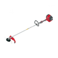
MONTAGGIO PROTEZIONE SICUREZZA (Fig. 1A-B)
Fissare la protezione (A) al tubo di trasmissione tramite
le viti (B), in una posizione che permetta di lavorare in
sicurezza.
NOTA: utilizzare la protezione (C, Fig. 1A) solamente
con la testina a li di nylon. La protezione (C) deve essere
ssata con la vite (G) alla protezione (A).
Per i dischi da legno (22-60-80 denti) utilizzare sempre
l’apposita protezione di metallo (Fig. 1B).
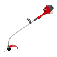
MONTAGGIO DISCO (Fig. 2)
Svitare in senso orario il bullone (A); togliere la coppa (D)
e la angia inferiore (E).Montare il disco (R) sulla angia
superiore (F) assicurandosi del giusto senso di rotazione.
Montare la angia inferiore (E), la coppa (D) ed avvitare il
bullone (A) in senso antiorario.
Inserire il perno in dotazione (L) , nell'apposito foro per
bloccare il disco e permettere il serraggio del bullone
(A, Fig. 2) a 2.5 kgm (25 Nm).
ATTENZIONE! - In caso di trasporto o rimessaggio
del decespugliatore, montare la protezione del disco (M)
cod. 4196086 come indicato nelle Fig. 4-5.
MONTAGGIO TESTINA A FILI DI NYLON (Fig. 3)
Inserire la angia superiore (F). Inserire il perno fermo
testina nell'apposito foro (L) ed avvitare in senso antiorario
la testina (N) con la sola forza delle mani.
MONTAGE PROTECTION-SECURITE (Fig. 1A-B)
Fixer la protection (A) au tuyau de transmission à l'aide
des vis (B) en position telle à vous permettre de travailler
en toute sécurité.
NOTE: utiliser la protection (C, Fig.1A) seulement avec la
tête l nylon. Le protecteur (C) doit être xé sur le carter
de protection (A) au moyen de la vis (G).
Pour les disques à bois (22-60-80 dents) utiliser toujours la
protéction spéciale en métal (Fig. 1B).
MONTAGE DU DISQUE (Fig. 2)
Dévissez le boulon dans le sens des aiguilles d'une montre
(A); otez le carter (D) et la bride inférieure (E). Montez le
disque (R) sur la bride supérieure (F), en vériant le bon
sens de rotation. Montez la bride inférieure (E), le carter (D)
et vissez le boulon (A) dans le sens contraire des aiguilles
d'une montre.
Enlez le goujon en dotation (L) dans le trou approprié pour
pouvoir bloquer le disque et serrer le boulon (A, Fig. 2) à
2.5 kgm (25 Nm).
ATTENTION! - En cas de transport ou de remisage de
la débroussailleuse, monter le carter de protection du disque
(M) p.n. 4196086 comme le montre les Fig. 4-5.
MONTAGE DE LA TETE AUX FILS DE NYLON (Fig. 3)
Enlez la bride supérieure (F). Enlez le goujon qui va bloquer
la tête dans son orice (L) et vissez à la main, dans le sens
contraire des aiguilles d'une montre, la tête (N).
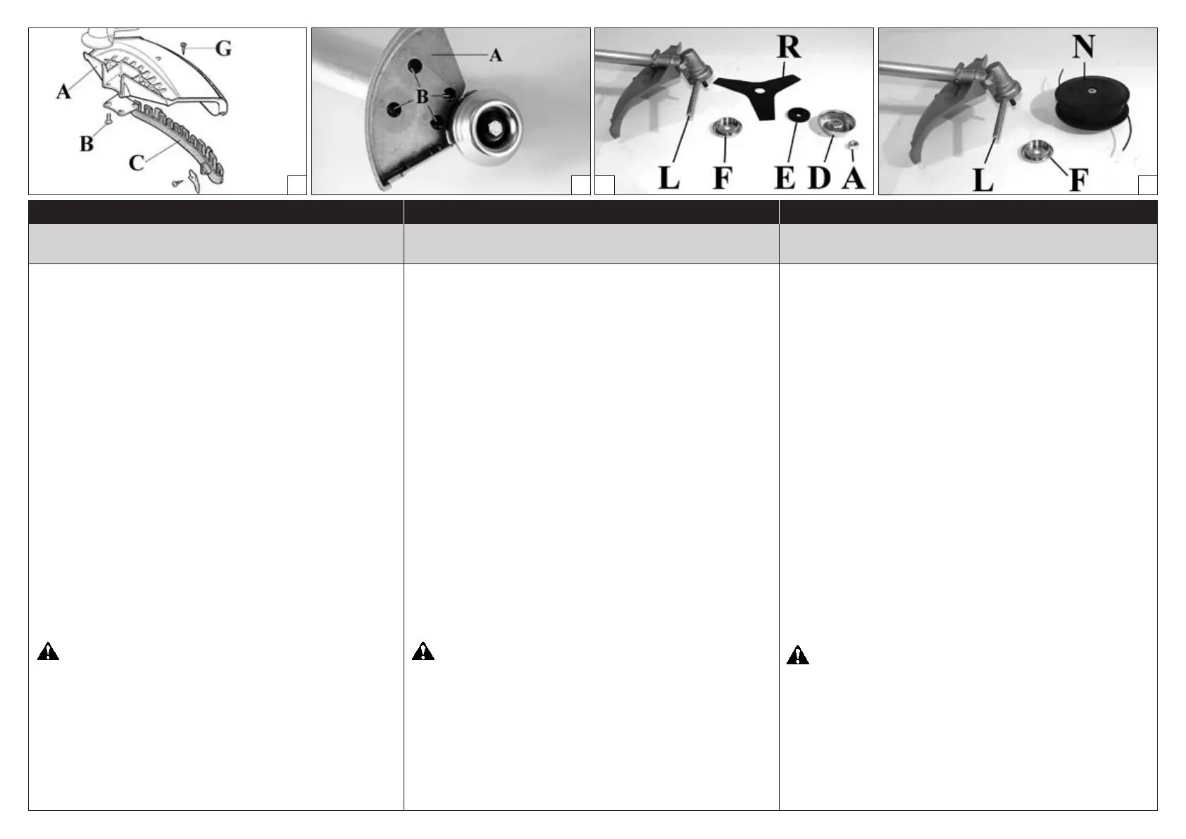
FITTING THE SAFETY GUARD (Fig. 1A-B)
Fit the blade guard (A) to the sha arm with screws in a
position allowing the operator to work safely (B).
NOTE: use the guard (C, Fig. 1A) only with nylon head.
Secure the guard (C) to the protection (A) by means of
the screw (G).
When using discs for wood (22-60-80 teeth), always set up
metal guard (see Fig. 1B).
FITTING THE DISK (Fig. 2)
Loosen the bolt (A) clockwise; remove cup (D) and lower
ange (E).
Fix the blade (R) onto the upper ange (F) making sure that
the rotation direction is correct.
Fix the lower ange (E), the cup (D) and tighten bolt (A)
anti-clockwise.
Put the pin provided (L) in the appropriate hole to block
the blade and allow the bolt (A, Fig. 2) to be tightened to
2.5 kgm (25 Nm).
WARNING! - Fit the disk protection (M) p.n. 4196086
as shown (Fig. 4-5) before transporting or storing the
brushcutter.
FITTING THE NYLON LINE HEAD (Fig. 3)
Put the upper (F) ange in place. Put the head xing
pin in the appropriate hole (L) and tighten the head (N)
anti-clockwise by hand.
3
21A
1B
L
 Loading...