14
Italiano FrançaisEnglish
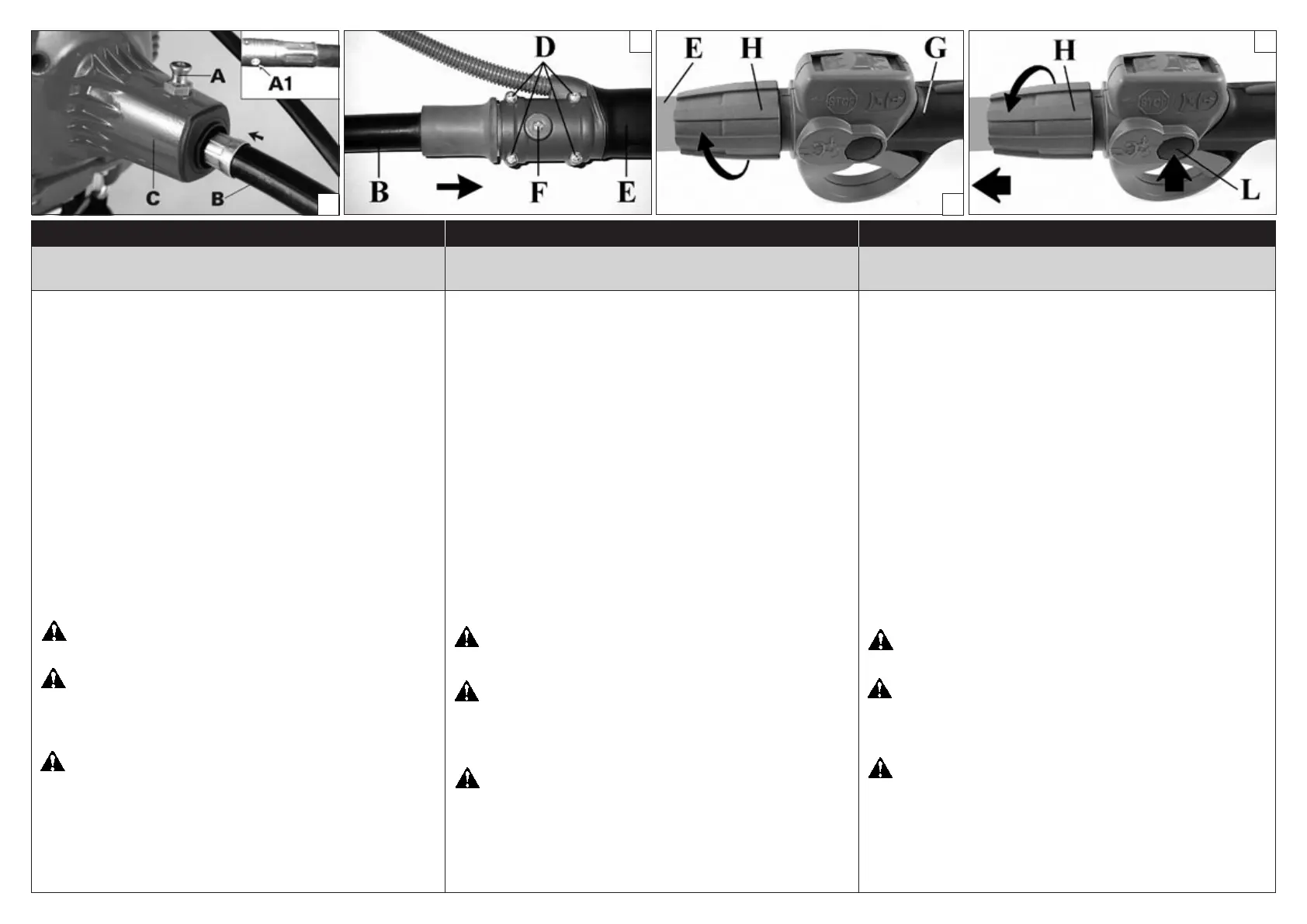
MOUNTING TRANSMISSION (Fig. 8-9)
Pull pin (A) and insert the end of exible pipe (B) into clutch
housing (C). Make sure the end of the exible coupling t. Insert
pin (A) into the end of the exible hole (A1, Fig. 8). Insert exible
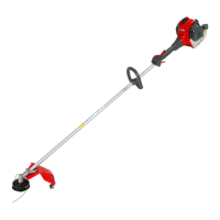
(B) into tube (E) making sure that exible sha end (B) is correctly
inserted into the rigid sha of transmission (Fig. 9). Fasten it with
screw (F) and screws (D).
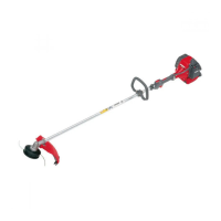
Insert the rigid drive sha tube (E, Fig.10) into the handle (G) and
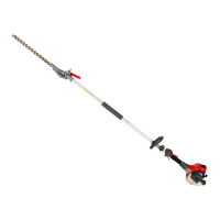
fasten it by screwing the ring nut. To disassemble it, it is necessary
to push the button (L, Fig.11) and rotate the ring nut (H) in the
opposite direction. Fasten cable tube to the exible pipe with the
two clips (N, Fig.13-14).
FITTING THE HANDLE (Figs. 12)
Fit the handle onto the sha arm and secure it using screws (A),
washers, and nuts. e handle position is calculated depending
on the requirements of the operator.
WARNING! - e handle must be xed between the two
notches (M, Fig.12) indicated on the drive sha tube.
WARNING: Make sure that all components are connected
properly and all screws tightened.
WORK PRECAUTIONS
WARNING! - Always follow the safety precautions. e
brush cutter must only be used to trim grass material. Do not
use the brush cutter as a lever to li, move or break objects,
nor lock it on xed supports. It is forbidden to apply tools or
applications that are not the ones indicated by the manufacturer
onto the brush cutter’s power take-o.
ASSEMBLAGGIO - NORME DI LAVORO ASSEMBLAGE - NORMES DE TRAVAILASSEMBLY - WORK PRECAUTIONS
MONTAGGIO TRASMISSIONE (Fig. 8-9)
Tirare il perno (A) ed inlare l'estremità del essibile (B) nella cua
frizione (C) assicurandosi che codolo e giunto siano ben incastrati.
Inlare il perno (A) nel foro (A1) del codolo terminale del essibile
(Fig. 8). Inserire il essibile (B) nel tubo (E) accertandosi che il terminale
dell'albero essibile (B) sia inserito correttamente nell'albero rigido
della trasmissione (Fig. 9). Fissarlo con la vite (F) e le viti (D).
Inserire il tubo di trasmissione rigido (E, Fig.10) nell’impugnatura
(G) e ssarlo avvitando la ghiera (H). Per lo smontaggio è necessario
premere il pulsante (L, Fig.11) e ruotare la ghiera (H) nella direzione
opposta.
Fissare con le due apposite clip (N, Fig.13-14) il tubo cavi al
essibile.
MONTAGGIO IMPUGNATURA (Fig. 12)
Montare l'impugnatura sul tubo di trasmissione e ssarla tramite viti
(A), rondelle e dadi. La posizione dell'impugnatura è registrabile in
funzione all'esigenza dell'operatore.
ATTENZIONE! – L’impugnatura deve essere ssata all’interno
delle due tacche (M, Fig.12) indicate sul tubo di trasmissione.
ATTENZIONE: Assicurarsi che tutti i componenti del
decespugliatore siano ben collegati e le viti serrate.
NORME DI LAVORO
ATTENZIONE! - Seguire sempre le norme di sicurezza. Il
decespugliatore deve essere utilizzato solamente per tagliare erba
o piccoli arbusti. È proibito tagliare altri tipi di materiale. Non
utilizzare il decespugliatore come leva per sollevare, spostare o
spezzare oggetti, né bloccarlo su sostegni ssi. È proibito applicare
alla presa di forza del decespugliatore utensili o applicazioni che
non siano quelli indicati dal costruttore.
MONTAGE DU TRANSMISSION (Fig. 8-9)
Tirer le tourillon (A) et enler l'extrémité du exible (B) dans le
carter d'embrayage (C) en s'assurant que l'embout du exible et la
bague d'accouplement soient encastrés. Enler le tourillon (A) dans
le trou de l'embout du exible (A1, Fig. 8). Insérer le exible (B) dans
la transmission (E); s'assurer que l'extrémité du exible (B) soit bien
monté dans la transmission (Fig. 9). Le xer à l’aide de la vis (F) et
la vis (D).
Installer le tuyau rigide de transmission (E, Fig. 10) dans la poignée
(G) et le xer en vissant la bague (H). Pour le démontage, appuyer
sur le bouton (L, Fig. 11) et tourner la bague (H) dans la direction
opposée.
Fixer le tuyau porte-câbles sur le exible à l’aide des deux clips
(N, Fig. 13-14).
MONTAGE DE LA POIGNEE (Fig. 12)
Montez la poignée sur le tuyau de transmission et xez-la avec les
vis (A), les rondelles et les écrous. La position de la poignée se règle
selon les exigences de l'opérateur.
ATTENTION! – Fixer la poignée à l’intérieur des deux crans
(M, Fig. 12) indiqués sur le tuyau de transmission.
ATTENTION: Veillez à ce que tous les composants soient
bien relié et les vis serrées.
NORMES DE TRAVAIL
ATTENTION! - Respectez toujours les normes de sécurité.
Le débroussailleuse ne doit être utilisé que pour tailler des herbe
ou de petits arbustes. Il est interdit de tailler autre chose. N’utilisez
pas le comme levier pour lever, déplacer ou fendre des objets et ne
le bloquez pas sur des supports xes. Il est interdit d’appliquer à
la prise de force du débroussailleuse des outils ou des applications
autres que ceux qui sont indiqués par le constructeur.
8
9
10
11