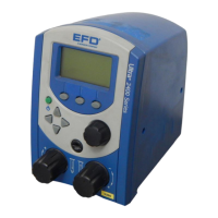
Features &
Controls:
Back Panel
13
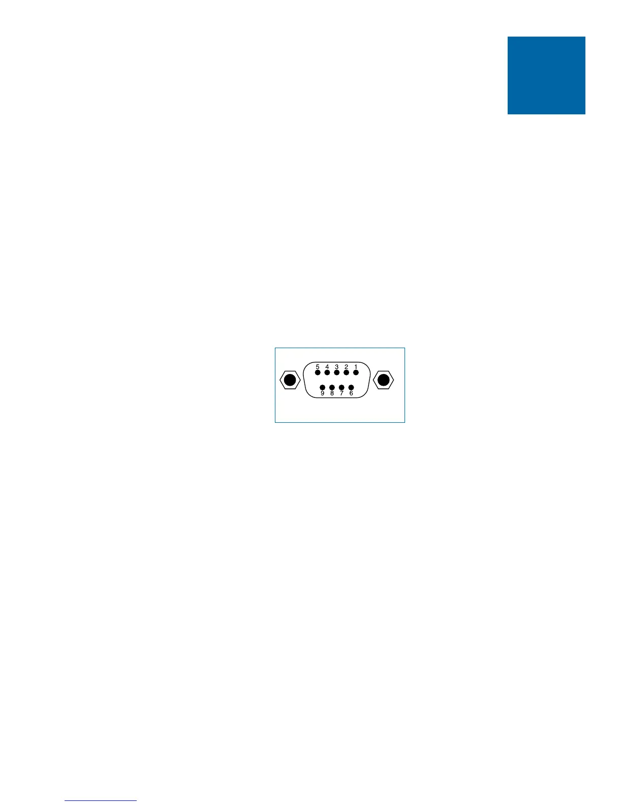
Input / Output 9 Pin Interface Connector
The Ultra 1400 may be initiated with a 5 to 24 VDC signal across pins 1 and 2.
The signal can be momentary (no less than 0.01 seconds) or maintained. A new
cycle will begin once power is removed and then applied again.
Upon completion of a dispense cycle, a solid state circuit closes and remains
closed until the next dispense cycle. Pins 3 and 4 of this circuit can be used to
signal back to a host computer, start another device in sequence or initiate other
operations that need to be tied into the completion of the dispense cycle. The
circuit is designed to operate between 5 and 24 VDC, 250mA maximum.
Pin Function
1. Voltage initiate + (5-24 VDC, 35mA maximum)
2. Voltage initiate —
3. End-of-cycle feedback output + ((5-24 VDC, 250mA maximum)
4. End-of-cycle feedback output —
5. Contact closure
6. Chassis ground
7. Contact closure
8. Not used
9. Not used
Note: A 9 pin male connector assembly is available. Specify EFD part #7154.


 To Next Page