PACKING LIST
PART NAME
QUANTITY
Brush Cutter
1
3-teeth blade with Sheath
1
Guard Assembly
1
Nut
1
Outer Flange
1
Hex Wrench
1
Multi-Function Wrench
1
Double-shoulder Strap
1
Operator’s Manual
1
DESCRIPTION
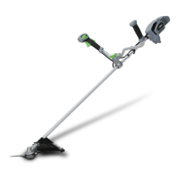
KNOW YOUR BRUSH CUTTER (Fig. A)
1. Speed Limiting Lever
2. Lock-off Lever
3. Wing Bolt
4. Trigger
5. Bike Handle
6. Shaft
7. Cutting Line
8. Guard Assembly
9. Trimmer Head
10. Sealing Screw
11. Shaft-locking Hole
12. Guard Accessory
13. Multi-Function Wrench
14. Hex Wrench
15. 3-teeth Blade
16. Outer Flange
17. Nut
18. Release Button
19. Rubber Pad Protection
20. Latch
21. Electric Contactsms
22. Ejection Mechanism
23. Strap Buckle
24. Hip-pad
WARNING: Never operate the tool without the
guard rmly in place. The guard must always be on the
tool to protect the user.
WARNING: When the tool is equipped with a
trimmer head, the guard accessory with line–cutting
blade should be mounted onto the guard. Failure to
comply will result in overly long cutting line and overload
the motor. Never use the trimmer head without guard
accessory.
ASSEMBLY
WARNING: If any parts are damaged or missing, do
not operate the brush cutter until the parts are replaced.
Use of the brush cutter with damaged or missing parts
could result in serious personal injury.
WARNING: Do not attempt to modify the brush
cutter or create accessories not recommended for use
with this product. Any such alteration or modication is
misuse and could result in a hazardous condition leading
to possibly serious personal injury.
WARNING: Always wear heavy gloves when
installing or removing the guard and doing any
maintenance on the 3-teeth blade/line-cutting blade. Be
careful of the line-cutting blade on the guard accessory /
3-teeth blade for protecting your hands from being injured
by both the blades.
WARNING: To prevent accidental starting that could
cause serious personal injury, always remove the battery
pack from the tool when assembling parts or transporting
the machine.
WARNING: Never operate the tool without the guard
and bike handle rmly in place. Failure to comply could
result in possible serious personal injury.
MOUNTING AND ADJUSTING THE BIKE HANDLE
The brush cutter is stored as shown in Fig. B. Firstly,
loosen the wing bolt on the connecting joint and then lift
the bike handle 180° around the shaft (Fig. C), turn it 90°
anticlockwise to make it face the bump head (Fig. D).
Lastly, move it back and forth to achieve a comfortable
working position and tighten the bolt.
NOTICE: Operating the machine with the bike handle
perpendicular to the shaft is only permitted.
 Loading...