16
10. Connection of external appliances & Controls
FACTORY CONNECTIONS
ZoneValve (SHW & SCH Volt Free Inputs)
When the Volt Free contacts are open circuit the boiler will
automatically stop heating the system.
These connections are factory tted, under NO circumstances
should any voltage be connected to these terminals as this will
result in damage to the boilers control electronics.
20,0
30,0
40,0
50,0
60,0
70,0
80,0
90,0
-20
-10010
20
Tch [°C]
Temp
outside
[°C]
n=4
n=6
n=8
n=10
n=12
n=14
n=16
n=18
n=20
n=22
n=24
n-no of heating curve (p=0)
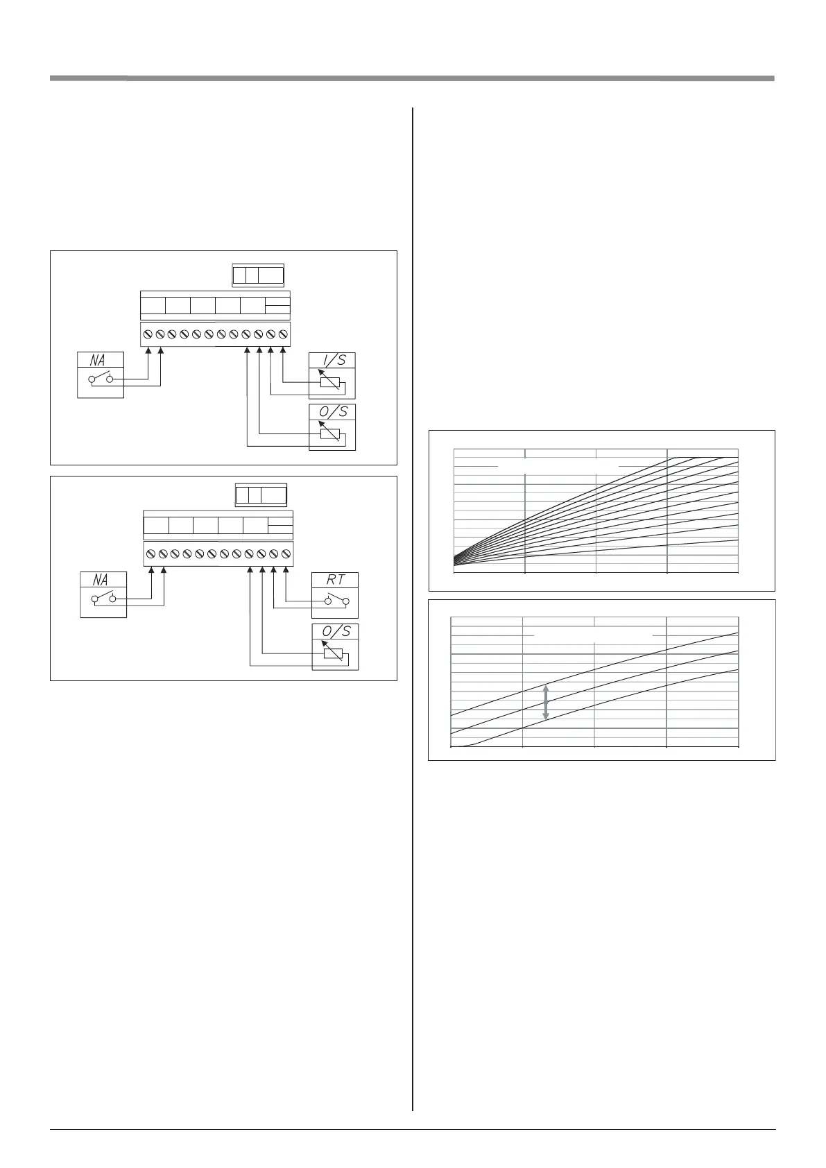
Master Appliance Control (NA)
The NA Connection is used when you have another high current
device installed within the property. i.e. Electric Shower or Water
Heater.
The shower sensor would be connected to the Main Water supply
feeding the shower, the switch wires from the ow sensor will then
be connected to the NA connections shown in Fig:1.
When the shower is in use the ow sensor will create an open
circuit on the NA connections. This will switch the boiler OFF
when the shower is in use protecting the power supply within
the property.
Temperature sensors
The temperature sensor’s cable should be kept as short as
possible. Do not run or twist the sensor cable alongside power
lines or other wiring.
To manually adjust the default CH temperature go to:
SETTINGS > BOILER TEMPERATURE [°C] and select your
appropriate value. The temperature of the CH installation can
be automatically adjusted when the weather compensation is
activated. This can be achieved by activating outside sensor -
O/S (see graph 1 and 2) which activates weather compensation.
To activate weather compensation go to:
CONFIGURATION - CENTRAL HEATING- REGULATION -
WEATHER COMP.
Install the outside temperature sensor (O/S) in the shade, on the
north or northwestern facade of the building, away from windows
and ventilators.
WEATHER COMP – boiler’s controller is responsible for adjusting
temperature in CH installation in accordance with external
(outside) temperature. When the temperature outside the
facility is low, heat demand within the facility is higher, whereas
while the temperature outside is high, analogically, there’s
no need to maintain high temperature within the installation.
The correlation between outside temperature and heating
installation’s temperature can be presented in a graphical
form of so called heating curve. The diagram below presents
a compilation of heating curves for the set point of room
temperature equal 22°C. Depending on the facility characteristics,
climate zone, and the type of heating installation one must select
appropriate heating curve (WEATHER COMP.) Heating curve no
14 (without the offset) is set as a default parameter. If the heating
curve needs to be changed, the OFFSET parameter has to be
adjusted accordingly. The graph below presents a heating curve
no 14 with the offset (-10°C and 10°C).
Tch [°C]
20,0
30,0
40,0
50,0
60,0
70,0
80,0
90,0
-20-1001020
n=14, p=10
n=14, p=0
n=14, p=-10
p - oset of heating curve
Temp
outside
[°C]
I/S
O/S
NA
A B AC
NA SHW SCH Thw O / S
RT
I / S
Fig:1
RT
O/S
NA
A B AC
NA SHW SCH Thw O / S
RT
I / S
Fig:2
Boiler’s operation is dependent on room’s temperature. Room
thermostat (RT) or NTC stat (I/S) have to be installed in the
representative room (such as a living room) away from radiators,
windows, doors, or vents.
• RT activated: the boiler operates according to the time
frames set in the daily/weekly programs; temperature in the
room can only be adjusted manually by using the wireless
thermostat
• I/S activated: the boiler operates according to the time
frames set in the daily/weekly programs and in accordance
with 3 optional temperature settings (selected in the daily
programs): COMFORT, COMOFRT +, COMFROT –
RT is set as a default sensor. In order to change it to NTC stat (I/S)
go to: CONFIGURATION>ROOM TEMP>TEMP SENSOR>I/S
Please note, that the sensors have to be physically
connected to the cable entry points - this can only be done
by an authorized person