15
9. Electrical Connection
ALL WIRING MUST BE CARRIED OUT IN ACCORDANCE
WITH CURRENT IEE BS7671 WIRING REGULATIONS.
ALL ELECTRICAL CONNECTIONS MUST BE MADE BY A
QUALIFIED ELECTRICIAN.
Load check must be taken into consideration when installing high
power boilers. This will be carried out by a qualied electrician.
There may be an additional requirement to upgrade the incoming
main fuse supplying the property if other high power devices are
used within the property. E.g. Electric Showers. If an electric
shower is present we recommend that a Shower Sensor is
installed within the system. This will cause an interrupt to the
boilers control signal when the shower is in use. The sensor will
disable the boiler protecting the electrical system from overload.
All boilers must be protected at the meter position with a 30mA
double pole RCD with a minimum of 3mm contact separation
accompanied by a suitably rated MCB. If the boiler is not tted
local to the meter position then an additional isolation switch
must be tted local to the boiler for each supply. If the property
is prone to lightening strikes or power cuts it is recommended
to install a suitable surge protection device to the boiler supply.
This will reduce the risk of damage to the boiler electronics during
these events.
THIS APPLIANCE MUST BE EARTHED.
All pipe-work must be earthed in accordance with the IEE BS7671
Wiring Regulations.
After completion of all electrical works, an electrical safety check
should be carried out i.e. short circuit, earth continuity, resistance
to earth and polarity check, and all relevant Test Certicates
completed and issued to the customer.
Never open the front cover of the boiler until all power supplies
to the boiler have been disconnected.
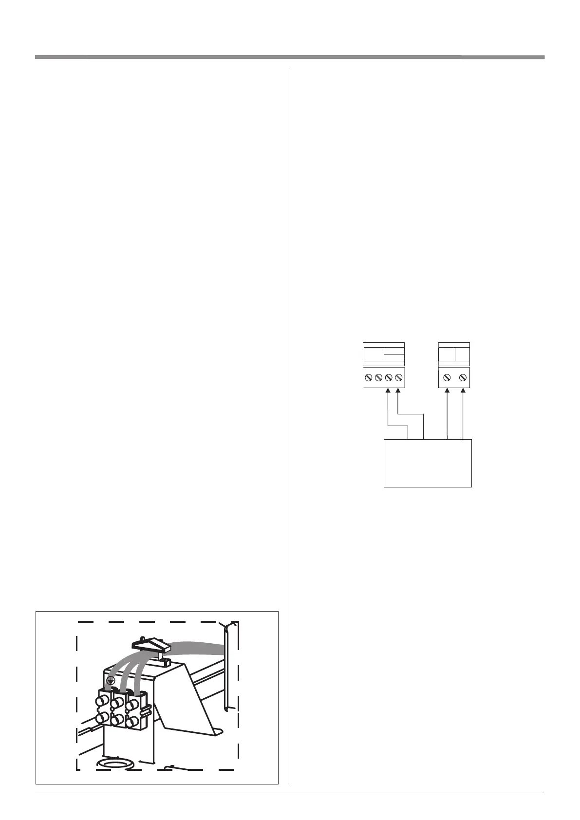
ELECTRICAL CONNECTIONS
The electrical supply cables can be routed into the boiler from
the top left hand side of the unit. Cable grommets are supplied
and tted to the boiler's cable entry point.
All cables should be secured to meet current regulations. The
boiler connections are clearly marked inside the boiler
L- Live, N - Neutral, E - Earth.
The supply is a permanent Feed connection to the boiler from
the mains supply and should never be isolated unless for
maintenance purposes.
The Boiler circuit RCD should be independent of all other
domestic circuits. The boiler supply cable should be calculated
by the means of a cable calculation in accordance with BS7671
by a suitably qualied electrician.
N
L
BOILER PROTECTION
The recommended protection for hard wired boilers are as
follows:
Model No Boiler size Protection (per phase)
Comet Combi 14.4kW 14.4kW BOILER 80 AMP Protection
Comet Combi 12kW 12kW BOILER 63 AMP Protection
Comet Combi 9kW 9kW BOILER 50 AMP Protection
EXTERNAL CONTROLS.
We recommend using EHC controls with our boilers. Connect
the RF receiver supplied with the boiler as shown below. The
receiver and room thermostat is precongured
The use of EHC controls ensures that boiler interlock is provided
as the use of TRV’s alone will not provide boiler interlock.
We recommend the use of TRV’s, however they must not be
used in the room that has the room thermostat tted.
O / S
RT
I / S
L N
1 2 3 L N
OFF COM ON
EC 10018
Wireless Receiver
Supply
BACK UP IMMERSION HEATER
The Comet Combi has a connection that allows you to install a
back up immersion heater if required. It is recommended that
this is connected via a local 16A double pole isolation switch
and connected to the consumer unit using the correct size cable
& 16A MCB