13
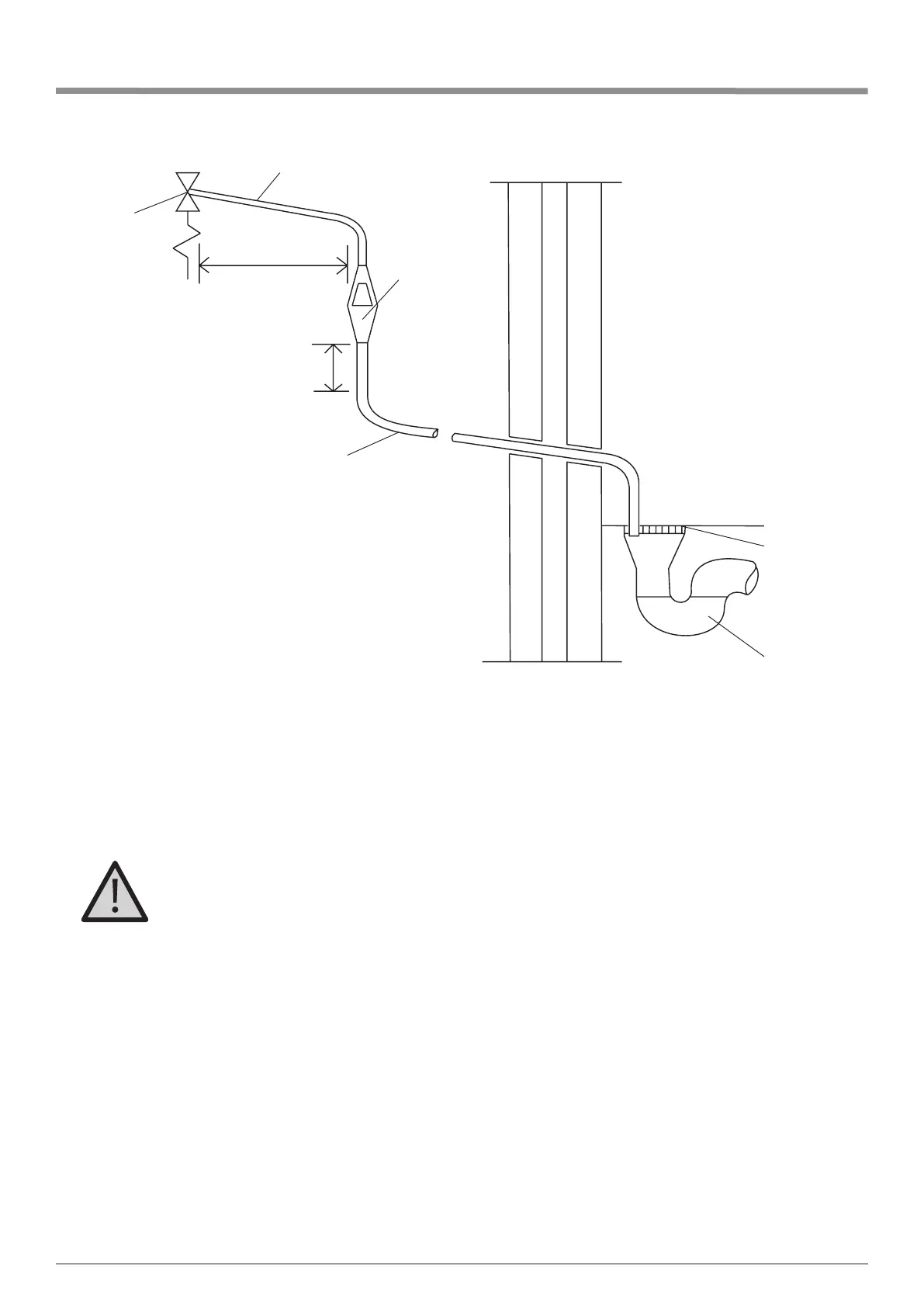
trapped gulley
xed
grating
Discharge below
xed grating
metal discharge pipe (D2) from
tundish, with continuous fall.
300mm
minimum
600mm maximum
safety device
temperature
relief valve
metal discharge pipe (D1) from
temperature relief valve to tundish
tundish
Note: The discharge will consist of scalding water and steam. Asphalt, roong felt and nonmetallic rainwater
goods may be damaged by such discharges.
Note: It is not acceptable to discharge straight into a soil pipe. Position the inlet control group so that the discharge
from both the two safety valves can be joined together via a 15mm end feed Tee. Connect the Tundish and route
the discharge pipe.
The discharge pipework must be routed in accordance with Part G3 of schedule 1 of the Building Regulations.
The information that follows is not exhaustive and if you are in doubt you should seek advice.
The two safety valves will only discharge water under fault conditions. When operating normally water will not be
discharged. The tundish should be vertical, located in the same space as the unvented hot water storage system
and be tted as close as possible and within 600mm of the safety device e.g. the temperature relief valve. The
discharge pipe (D2) from the tundish should terminate in a safe place where there is no risk to persons in the vicinity
of the discharge, be of metal and:
A) Be at least one pipe size larger than the nominal outlet size of the safety device unless its total equivalent
hydraulic resistance exceeds that of a straight pipe 9m long i.e. discharge pipes between 9m and 18m equivalent
resistance length should be at least two sizes larger than the nominal outlet size of the safety device, between 18
and 27m at least 3 sizes larger, and so on. Bends must be taken into account in calculating the ow resistance.
Refer to diagram 1, Table 1 and the worked example. An alternative approach for sizing discharge pipes would
be to follow BS6700 Specication for design installation, testing and maintenance of services supplying water
for domestic use within buildings and their curtilages.
B) Have a vertical section of pipe at least 300mm long, below the tundish before any elbows or bends in the
pipework.
C) Be installed with a continuous fall.
D) It is preferable for the discharge to be visible at both the tundish and the nal point of discharge but where this
is not possible or practically difcult there should be clear visibility at one or other of these locations. Examples
of acceptable discharge arrangements are:
Theabovediagramisofatypicaldischargepipearrangement. (extract from Building Regulation G3)
8. Installation: discharge arrangement