8
GB-063C_f.615
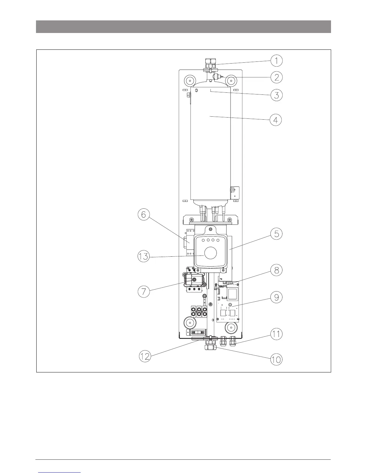
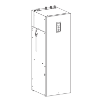
Figure 1
1 - Flow Outlet Connection
2 - Run Dry Sensor
3 - Outlet Temperature Sensor
4 - Heat Exchanger
5 - Power Board
6 - Contactor
7 - WT3 Safety Thermal Cut-Out
8 - Inlet Temperature Sensor
9 - Control board
10 - Return Inlet Connection
11 - Pump & Control Cable Entry Points
12 - Main Power Entry Point
13 - Front Control Panel
1
2
3
6
5
7
8
9
10
11
12
13
4
!
The boiler is tted with a safety temperature cut-out that protects the boiler from failure. The
safety temperature cut-out (Item 7) cuts the power to the boiler if the temperature reaches approx 100°C.
if this occurs the boiler will shut off the main power to the unit. A service engineer will be required to
re-set the boiler. However further investigation will be required to identify the cause of the fault.
BOILER INTERNAL LAYOUT