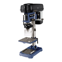
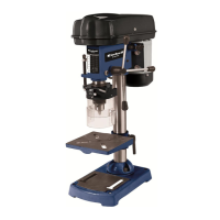
5. Technical data
BT-BD 401
Nominal input voltage 230V ~ 50 Hz
Power rating 350 W
Operating mode S2 15 min.
Motor speed 1,400 rpm
Output speed 580 - 2,650 rpm
Speed levels 5
Drill chuck mount B 16
Scroll chuck Ø 1.5 - 13 mm
Max. shaft diameter 13 mm
Reach 104 mm
Drill depth 50 mm
Pillar diameter 46 mm
Height 590 mm
Weight 18 kg
L
pA
sound pressure level 61.5 dB(A)
L
WA
sound power level 74.5 dB(A)
K
pA
uncertainty 3 dB
K
WA
uncertainty 3 dB
BT-BD 501
Nominal input voltage 230V ~ 50 Hz
Power rating 500 W
Operating mode S2 15 min.
Motor speed 1,400 rpm
Output speed 280 – 2,650 rpm
Speed levels 9
Drill chuck mount B 16
Scroll chuck Ø 3 - 16 mm
Max. shaft diameter 16 mm
Reach 115 mm
Drill depth 50 mm
Pillar diameter 46 mm
Height 650 mm
Weight 21.5 kg
L
pA
sound pressure level 61.5 dB(A)
L
WA
sound power level 74.5 dB(A)
K
pA
uncertainty 3 dB
K
WA
uncertainty 3 dB
Sound and vibration
Sound and vibration values were measured in
accordance with EN 61029.
Load factor:
A load factor of S2 15 min (intermittent periodic duty)
means that you may operate the motor continuously
at its nominal power level (350/500 W) for no longer
than the time stipulated on the specifications label (15
minutes ON period).
If you fail to observe this time limit the motor will
overheat. During the OFF period the motor will cool
again to its starting temperature.
“The quoted values are emission values and not
necessarily reliable workplace values. Although there
is a correlation between emission and immission
levels it is impossible to draw any certain conclusions
as to the need for additional precautions. Factors with
a potential influence on the actual immission level at
the workplace include the duration of impact, the type
of room, and other sources of noise etc., e.g. the
number of machines and other neighboring
operations. Reliable workplace values may also vary
from country to country. With this information the user
should at least be able to make a better assessment
of the dangers and risks involved.”
6. Before starting the equipment
6.1. Assembling the machine
Position the machine base (1).
Fasten mounting flange with pillar (2) using three
screws (3) and washers to drill base (1).
Push the drill table (4) with drill table clamp shaft
onto the pillar (2) (Fig. 4). Lock the drill table into
the desired position using the clamping screw (5).
Place drill head (6) with V-belt cover (7) and
motor (8) onto the drill pillar and fasten using the
Allen screws (20).
Screw the three ball-shaped handles (9) onto the
feeder cross handle.
Note: All bare parts are greased in order to protect
them from corrosion. Before mounting the drill chuck
(10) onto the spindle (11), both parts must be
completely degreased using an environmentally
friendly solvent. This ensures optimal transmission of
power.
11
GB