- 32 -
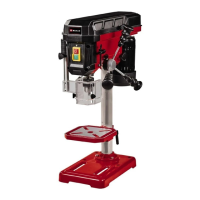
5.1 Assembling the machine (Fig. 3-8)
•
Place the base plate (1) in the desired positi-
on.
•
Fasten the pillar (2) with flange using the sup-
plied screws (3). (Fig. 3)
•
Slide the drill table (4) onto the pillar from
above (Fig. 4). Secure the drill table at the
desired height with the tightening screw (5).
•
Finally mount the complete machine head (6)
on the pillar.
Note: If possible, lift the machine head onto
the pillar together with another person.
•
Align the machine head so that it is vertical to
the base plate and secure the pre-fitted screw
a with the help of the supplied hex key (30)
(Fig. 5).
•
Screw the 3 supplied handles (9) in the hand-
le mounts. (Fig. 6)
•
Screw the clamping lever (17) in place as
shown in Fig. 7.
•
Before you fit the drill chuck (10) to the drill
chuck mount (24), check that both parts are
clean. Then insert the drill chuck into the
drill chuck mount by pressing it in firmly and
check that the chuck is secure (Fig. 8).
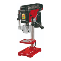
5.2 Installing the machine (Fig. 1)
Before you use the drill for the rst time it must be
permanently xed in position. Use both mounting
holes (12) in the base plate to do this. Ensure that
the equipment is freely accessible for operation,
adjustment and maintenance.
Note: The xing screws may only be tightened
to a point where they do not distort or deform the
base plate. Excessive tension can lead to fracture.
5.3. Folding chip guard (Fig. 9-12)
•
Before fitting the chip guard (13) you must
move the drill table (4) to its lowest position
(see section 6.7 Setting the height of the drill
table).
•
Remove the fastening rail (23), the stop screw
(20) and the stop washer b (Fig. 9).
•
Push the fastening rail into the holder for the
chip guard (21) (Fig. 10).
Note: While you push the fastening rail into
the holder, the securing screw for the chip
guard (22) must point to the front as shown
in Fig. 12. Only then will you be able to fully
close the chip guard when it is in the installed
state.
•
Now re-fit the stop screw with the stop washer
b to the fastening rail (Fig. 11).
•
The height of the chip guard is infinitely adjus-
table and can be fastened using the securing
screw (22) (Fig. 12).
•
The chip guard must be flipped to the side to
enable bits to be changed.
5.4 Prior to using the machine for the rst
time
Ensure that the voltage of the mains supply com-
plies with the specications on the rating plate.
Connect the equipment only to a socket with the
properly installed earthing contact. The drill is
equipped with a no-volt trip that is designed to
protect the operator from an undesired restart fol-
lowing a drop in voltage. Should this happen, the
equipment must be physically restarted.
6. Operation
6.1 General (Fig. 12)
To switch on the equipment, push in the green
On button “I” (18); the drill starts up. To switch o,
press the red O button “O” (19); the drill shuts
down. Ensure that you do not overload the equip-
ment.
If the sound of the motor drops in pitch during
operation, it is being overloaded.
Do not overload the equipment to the point where
the motor comes to a standstill.
6.2 Fitting tools to the drill chuck (Fig. 1)
Make sure that the power plug is removed from
the socket-outlet before changing tools. Only cy-
lindrical tools with the stipulated maximum shaft
diameter may be clamped in the drill chuck (10).
Only use a tool that is sharp and free of defects.
Do not use tools whose shaft is damaged or
which are deformed or awed in any other way.
Use only accessories and attachments that are
specied in the operating instructions or have
been approved by the manufacturer. If the pillar
drill becomes jammed, switch o the machine
and return the drill to its starting position.
6.3 How to use the scroll chuck (Fig. 13)
The pillar drill is equipped with a scroll chuck. To
insert a drill bit you must rst swing the chip guard
(13) to the side. Then insert the bit and tighten
the chuck (10) with the supplied chuck key (27).
Hazard! Do not leave the chuck key inserted. An
inserted chuck key would be catapulted into the
surroundings, with a high risk of injury.
Anl_SA_TC_BD_450_SPK8.indb 32Anl_SA_TC_BD_450_SPK8.indb 32 19.07.2022 13:18:2919.07.2022 13:18:29