OPERATION MANUAL DK 50 4x2V/M
NP-DK50 4x2V-M-EN-16_11-2015 11/2015
7
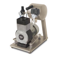
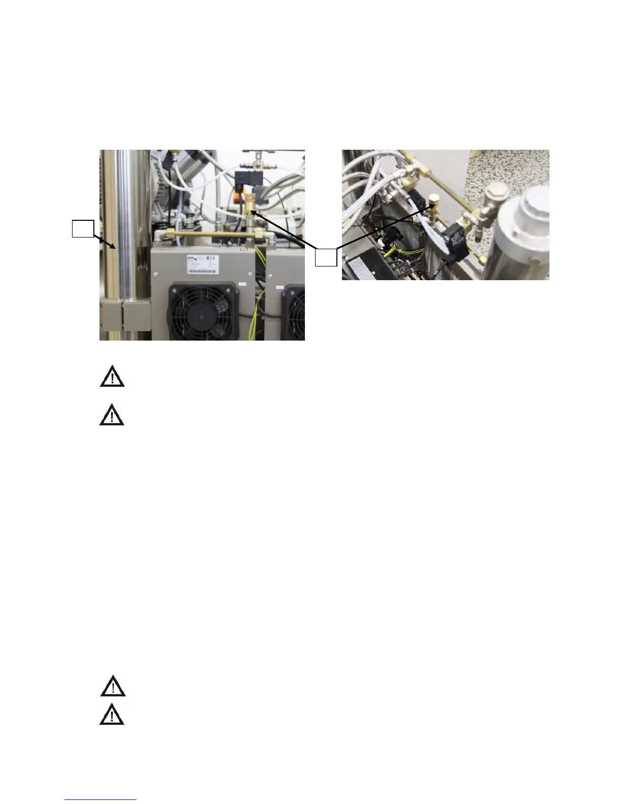
1. Safety valve
2. Dryer
Fig.1
Connect to output of ball valve with internal G3/4“ thread distribution of compressed air.
Connect electric supply of required parameters to input terminals of circuit breaker FA1 and
bridge of PE and N.
The safety valve is mounted into the pressure circuit of the compressors in front input solenoide valve.
In case of an additional assembly (Fig. 1) it is necessary to replace the „T“-piece G3/8“ by „X“-piece
(cross) G3/8“-1/4“ and sealing Cu 4KA-078.
For an additional assembly of the safety valve, it is necessary to adhere to the safety
measures referred to in the paragraph Product maintenance .
At the connection of device to distribution system TN-S, do not interconnect reset
bridges of PE and N !
7. PUTTING THE PRODUCT INTO OPERATION
After assembly and connection of the device to electric mains of 3 x 400V+N+PE, put both circuit
breakers FA5 and FA6 to I position. Then switch on switch of pressure switch SP, when all four
compressors shall be put into operation, two immediately (M1, M2) and two (M3,M4) after time delay
of 1-2 s. (adjusted at KT1). AS main switch, you may still use switch of pressure switch SP. After the
first connection of compressor to mains voltage, the pressure in common air chamber shall be
increased up to the value of switching off pressure SP (8 bar), when compressors shall be
automatically switched off. In further cycles, the compressors work in automatic mode, i.e. according
to the consumption of compressed air the compressors are switched on (at 0.6 MPa) and switched off
by pressure switch SP.
After prolonged operation of compressors or when temperature is increased at surface of engines
above 40
o
C, thermal switches ST1 ( ST2 ) shall switch on cooling ventilators EV1 and EV2 ( EV3 and
EV4 ) thus cooling of compressor aggregates shall be ensured even during their break. After
decreasing temperature in the space around engine under cca 35
o
C the relevant ventilators shall
again switch off. ventilators EV1 and EV2 ( EV3 and EV4 ) are always switched on at the same time
with engines of compressors M1 and M2 ( M3 and M4 ).
Such installed compressors do not require any attendance during operation. In next mode, the
compressors work automatically.
Pressure switch located on the air chamber has beforehand adjusted pressure value.
It is not allowed to change this value by readjusting of pressure switch.
The pressure presetting of safety valve is forbidden!
1
2
 Loading...