- 7 -
STEP 9: PUMP – CONNECTING
CABLES
D-RGB
Connector
VDG Connector
4-pin Connector
STEP A:
Plug the 4-pin PWM connector of the pump to
the motherboard.
D-RGB Header
RGB Header
STEP B:
Plug the 3-pin connector of the pump’s D-RGB LED
light to the D-RGB HEADER on the motherboard.
The LED will work if the pin layout on the header is
as follows: +5V, Digital, Empty, Ground. With some
motherboards, you can alternatively use a VDG
connector instead of a D-RGB to connect the LED.
Please ensure that the arrow indicated on
the connector is plugged into the +5V line
as indicated on your motherboard. If you
put LED Diode to the 12V RGB HEADER
you can damage the LEDs.
Connector is the same on D-RGB and RGB
versions, but D-RGB version has 3 cables
from connector to PCB; RGB version has
4 cables. If you connect D-RGB led to
ordinary RGB header you can damage
your motherboard or LED strip.
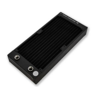
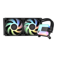
STEP 8: INSTALLING THE RADIATOR
AND FANS ASSEMBLY INTO THE PC
CASE
Attach the assembly of the radiator and the
fan(-s) to the PC case with the UNC 6-32 x
6mm screws.
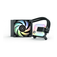
EK-AIO 120 D-RGB
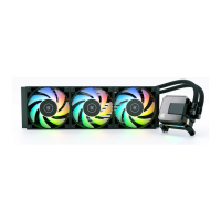
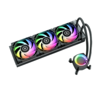
EK-AIO 240 D-RGB /
EK-AIO 280 D-RGB
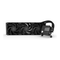
EK-AIO 360 D-RGB
UNC 6-32 x 6 mm
(4x)
UNC 6-32 x 6 mm
(8x)
UNC 6-32 x 6 mm
(12x)
Radiator on top (recommended)
Vertical placement of the radiator with
tubing at the bottom (recommended)
Vertical placement of the radiator with
tubing at the top (not optimal)
Radiator at the bottom (should be avoided)
 Loading...