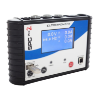
Power Indicators:
The blue ‘power’ indicator will illuminate when the unit is connected to a valid
supply voltage (175-300 VAC). When the led is ‘off’ the SPCPro2 is operating
from battery power.
Logging Indication:
The red ‘logging’ indicator provides a short flash every few seconds whilst a
survey is taking place.
USB Connection Socket:
The SPCPro2 is connected to a PC from this port using a standard USB ‘A to B’
interface cable (supplied).
SETTING UP
Refer to the ‘PowerPackPro’ section of this manual for detailed instructions on
setting up the SPCPro2 prior to commencing operation.
CONNECTING UP
Voltage Connection:
Mains connection should be carried out via the supplied lead to a 230VAC wall
socket. If a wall socket of the correct type is not available refer to Elcomponent
for availability of alternative connection cables.
Warning: The connected voltage must not exceed 300VAC.
Exceeding the voltage will damage the instrument and could be
hazardous.
Current Connection:
The SPCPro2 is suitable for use on both single phase and three phase supplies.
Current measurement connections are made by clipping the flex-type CTs around
the conductors as shown in the following diagrams and pictures.
NOTE: It is important to be able to identify cables correctly when
carrying out electrical surveys. Failure to do so may compromise the
accuracy of results obtained. Please refer to Appendix 2 for
information on UK wiring connections. If you are working outside the
UK, additional information may be required.