13-16
TROUBLESHOOTING
SM OU12HP 2-E.2 GB
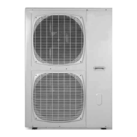
11) Connect the “COM“ side of the tester to the “N” terminal
of driver and the “V:” side of the tester to “T/RB” of
driver, measure the diode voltage.
Voltage should be “OL” (Over Load).
Replacing driver - (14.1.15)
13.5.5.2 6HP
Remove all the terminals of the driver before checking.
If items 1) to 8) are performed and the results are satisfactory, driver is normal.
Use a digital multi meter in diode checking function
1)
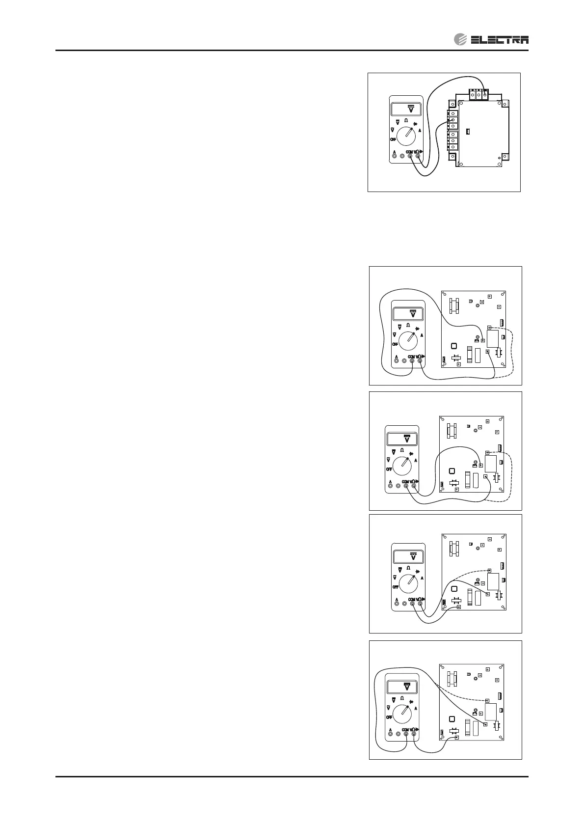
Connect the “COM“ side of the tester to the “CAPA-”
terminal of driver and the “V:” side of the tester to “LIVE”
and “NEUTRAL” of driver, measure the diode voltage.
Voltage should be “OL” (Over Load).
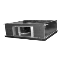
2)
Connect the “V:” side of the tester to the “CAPA-”
terminal of driver and the “COM” side of the tester to
“LIVE” and “NEUTRAL” of driver, measure the diode
voltage.
Voltage should be 0.4~0.8VDC.
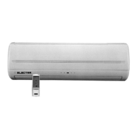
3)
Connect the “COM“ side of the tester to the “CAPA+”
terminal of driver and the “V:” side of the tester to “LIVE”
and "NEUTRAL" of driver, measure the diode voltage.
Voltage should be 0.4~0.8VDC.
4)
Connect the “V:” side of the tester to the “CAPA+”
terminal of driver and the “COM” side of the tester to
“LIVE” and "NEUTRAL" of driver, measure the diode
voltage.
Voltage should be “OL” (Over Load).
RB
S
R
P1
N
P
U
V
W
OL
OL
N
V
W
U
L
CAPA-
CAPA+
W
U
CAPA-
L
N
V
CAPA+
0.5
0.5
W
U
CAPA-
L
N
V
CAPA+
OL
W
U
CAPA-
L
N
V
CAPA+