13-17
TROUBLESHOOTING
SM OU12HP 2-E.2 GB
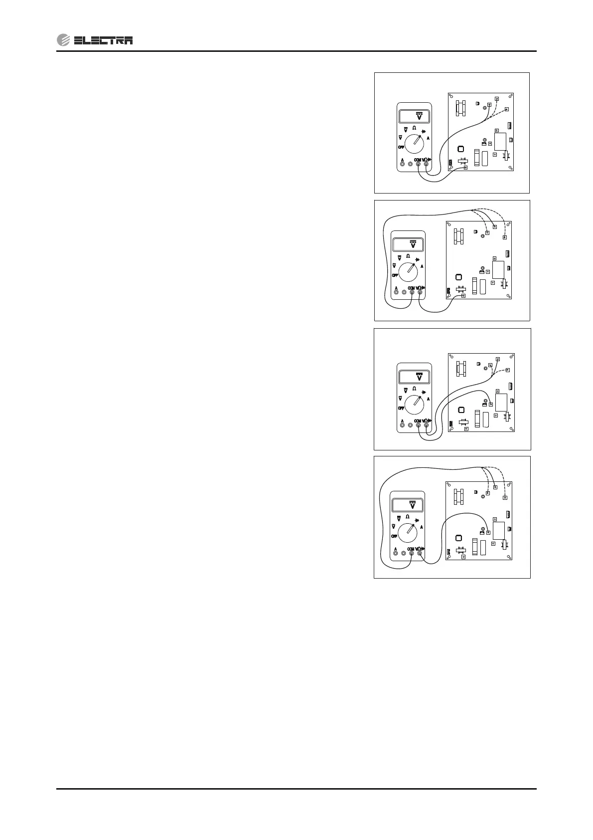
5)
Connect the “COM“ side of the tester to the “CAPA+”
terminal of driver and the “V:” side of the tester to “U”,
“V” and “W” of driver, measure the diode voltage.
Voltage should be 0.4~0.8VDC.
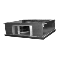
6)
Connect the “V:” side of the tester to the “CAPA+”
terminal of driver and the “COM” side of the tester to “U”,
“V” and “W” of driver, measure the diode voltage.
Voltage should be “OL” (Over Load).
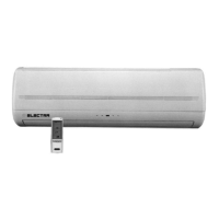
7)
Connect the “COM“ side of the tester to the “CAPA-”
terminal of driver and the “V:” side of the tester to “U”,
“V” and “W” of driver, measure the diode voltage.
Voltage should be “OL” (Over Load).
8)
Connect the “V:” side of the tester to the “CAPA-”
terminal of driver and the “COM” side of the tester to “U”,
“V” and “W” of driver, measure the diode voltage.
Voltage should be 0.4~0.8VDC.
Replacing driver - (14.1.15.2)
13.5.6 Checking PFC Chock coil
1) Check PFC chock connections – repair if needed.
2) Visually check to see any burn marks on the wires – replace the chock(s) if needed.
3) Disconnect the chock from the driver and check if the 2 ending wires of each chock are shorted
(continuity check) – if they are NOT shorted replace the chock(s), if they are shorted – check the
driver (13.5.5).
Replacing PFC chock - (14.1.17)
13.5.7 Checking DC Capacitors
1) Check visually for burn marks on the capacitor PCB and the capacitors for swelling casing
– replace if needed.
0.5
W
U
CAPA-
L
N
V
CAPA+
OL
W
U
CAPA-
L
N
V
CAPA+
OL
W
U
L
N
V
CAPA-
CAPA+
0.5
W
U
CAPA-
L
N
V
CAPA+