1 2 3
Unité
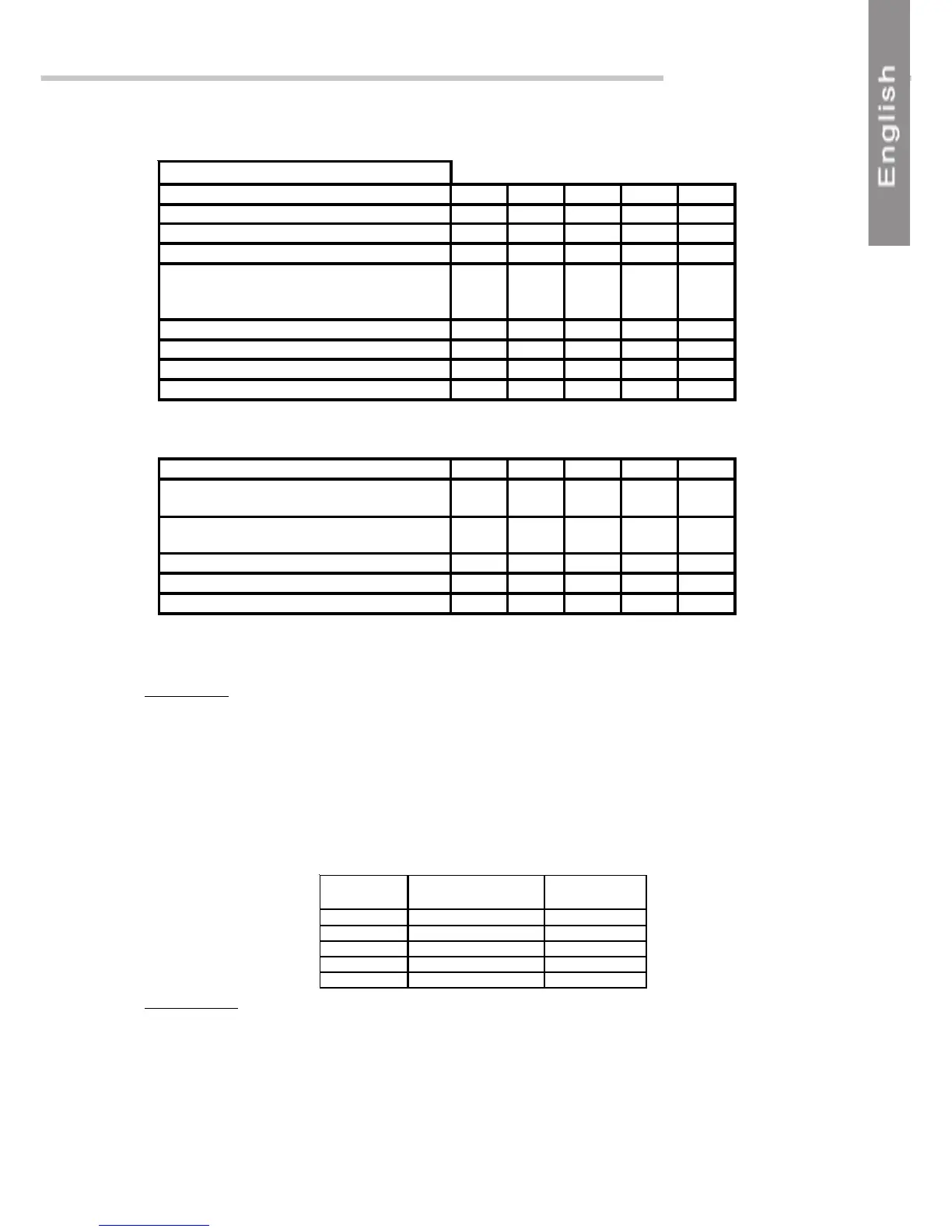
Total nominal current A 12.2 20.7 27.3 33.9
Total maximum current A 15 23.5 30.1 36.7
Total starting current A 70 78.5 85.1 91.7
Fuse rating aM/VDE A 20/20 25/25 32/35 40/50
3G type power supply cable section mm² 2,5 6 10 10
CONFIGURATION EXAMPLE Unité A B C D
Max. current / ST w/o elec. heating A 1 X 1,5 0 0 0
Max current / ST with elec. heating (UNIT A) A ¬0 1 X 10,2 1 X 10,2 1 X 10,2
Max. current / ST w/o elec. heating A 2 X 1,5 2 X 1,5¬¬1 X 1,5¬ 0
Max current / ST with elec. heating (UNIT B) A 0 0 1 X 6,6 2 X 6,6
Fuse rating with electrical heating aM A 0 10 10 /10 10 / 20
6G type ST connecting cable section mm² 1,5 1,5 1,5 1,5
UNIT A: FUSE QF1
UNIT B: FUSE QF23
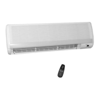
ELECTRICAL CONNECTIONS TO ST UNITS
Indoors unit type Electrical heating capacity
(W)
Maximum current
(A)
PXD 9 1250 6,6
ECF 9 900 4,7
LS 11 1600 8,5
PXD 12 1250 6,6
ECF 11 900 4,7
IMPORIMPOR
IMPORIMPOR
IMPOR
TT
TT
T
ANTANT
ANTANT
ANT
* The installer must comply with all local standards. The cable section must be suitable for the
installation method, the type of cable insulation and the cable length.
These values are provided for information purposes only. They must be verified and adapted
in relation to existing standards.
These values may vary in relation to the type of installation and the choice of conductors.
Comments:
This data is given for the most unfavourable installation in terms of maximum current
draw: 1 LS11 on circuit A / 2 PXD9 on circuit B
Case with 3 cassettes (2 x ECF9 + 2 x ECF11):
8A fuse is to be provided for unit A
16A fuse is to be provided for unit B .
Electrical heating details for each ST for determining the appropriate fuse rating