ELECTRO FREEZE Model FM8
16
184979-17
2345678901234
2345678901234
2345678901234
2345678901234
2345678901234
2345678901234
2345678901234
2345678901234
2345678901234
2345678901234
2345678901234
2345678901234
2345678901234
2345678901234
2345678901234
2345678901234
2345678901234
2345678901234
2345678901234
2345678901234
2345678901234
2345678901234
2345678901234
2345678901234
2345678901234
2345678901234
2345678901234
2345678901234
2345678901234
2345678901234
2345678901234
2345678901234
2345678901234
2345678901234
2345678901234
2345678901234
2345678901234
2345678901234
2345678901234
2345678901234
2345678901234
2345678901234
2345678901234
2345678901234
2345678901234
2345678901234
2345678901234
2345678901234
2345678901234
2345678901234
2345678901234
2345678901234
2345678901234
2345678901234
2345678901234
2345678901234
2345678901234
2345678901234
2345678901234
2345678901234
2345678901234
2345678901234
2345678901234
2345678901234
2345678901234
2345678901234
2345678901234
2345678901234
2345678901234
2345678901234
2345678901234
2345678901234
2345678901234
2345678901234
2345678901234
2345678901234
2345678901234
2345678901234
2345678901234
2345678901234
2345678901234
2345678901234
2345678901234
2345678901234
2345678901234
2345678901234
2345678901234
2345678901234
2345678901234
2345678901234
2345678901234
2345678901234
2345678901234
2345678901234
2345678901234
2345678901234
2345678901234
2345678901234
2345678901234
2345678901234
2345678901234
2345678901234
2345678901234
2345678901234
2345678901234
2345678901234
2345678901234
2345678901234
2345678901234
2345678901234
2345678901234
2345678901234
2345678901234
2345678901234
2345678901234
2345678901234
2345678901234
2345678901234
2345678901234
2345678901234
2345678901234
2345678901234
2345678901234
2345678901234
2345678901234
2345678901234
2345678901234
2345678901234
2345678901234
2345678901234
2345678901234
2345678901234
2345678901234
2345678901234
2345678901234
2345678901234
2345678901234
2345678901234
2345678901234
2345678901234
2345678901234
2345678901234
2345678901234
2345678901234
2345678901234
2345678901234
2345678901234
2345678901234
2345678901234
2345678901234
2345678901234
2345678901234
2345678901234
2345678901234
2345678901234
2345678901234
2345678901234
2345678901234
2345678901234
2345678901234
2345678901234
2345678901234
2345678901234
2345678901234
2345678901234
2345678901234
2345678901234
2345678901234
2345678901234
2345678901234
2345678901234
2345678901234
2345678901234
2345678901234
2345678901234
2345678901234
2345678901234
2345678901234
2345678901234
2345678901234
2345678901234
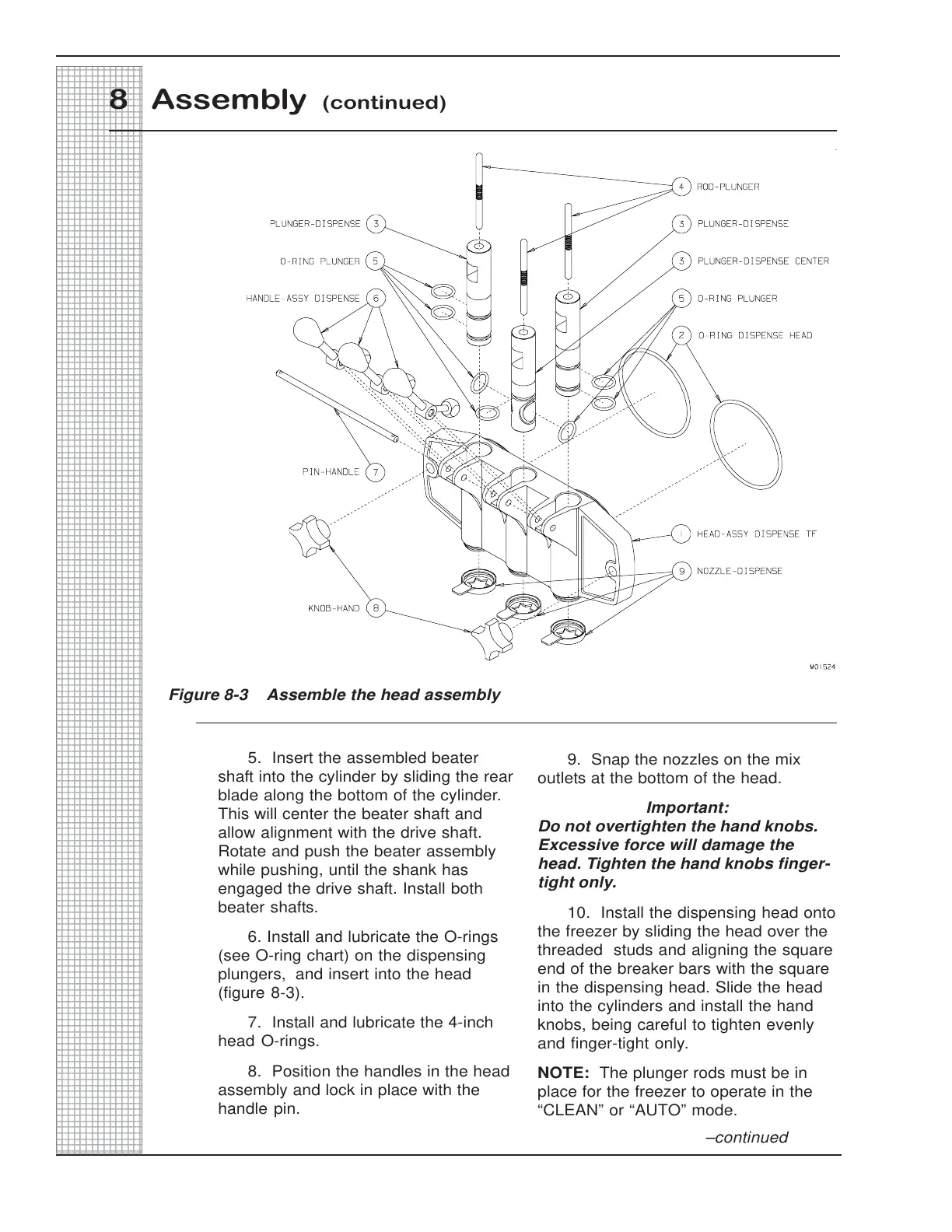
8 Assembly (continued)
Figure 8-3 Assemble the head assembly
5. Insert the assembled beater
shaft into the cylinder by sliding the rear
blade along the bottom of the cylinder.
This will center the beater shaft and
allow alignment with the drive shaft.
Rotate and push the beater assembly
while pushing, until the shank has
engaged the drive shaft. Install both
beater shafts.
6. Install and lubricate the O-rings
(see O-ring chart) on the dispensing
plungers, and insert into the head
(figure 8-3).
7. Install and lubricate the 4-inch
head O-rings.
8. Position the handles in the head
assembly and lock in place with the
handle pin.
9. Snap the nozzles on the mix
outlets at the bottom of the head.
Important:
Do not overtighten the hand knobs.
Excessive force will damage the
head. Tighten the hand knobs finger-
tight only.
10. Install the dispensing head onto
the freezer by sliding the head over the
threaded studs and aligning the square
end of the breaker bars with the square
in the dispensing head. Slide the head
into the cylinders and install the hand
knobs, being careful to tighten evenly
and finger-tight only.
NOTE: The plunger rods must be in
place for the freezer to operate in the
“CLEAN” or “AUTO” mode.
–continued
 Loading...