EVID
EVID
TMTM
Owner’s ManualOwner’s Manual
99
Product DescriptionProduct Description
Step 4: Mount the Speaker to theStep 4: Mount the Speaker to the
BracketBracket
First remove the two Phillips-head screwsFirst remove the two Phillips-head screws
on the rear of the enclosure. Use theon the rear of the enclosure. Use the
supplied eyebolt to mount one mountingsupplied eyebolt to mount one mounting
clip to the top of the speaker as shown inclip to the top of the speaker as shown in
Figure 24. Check to make sure that theFigure 24. Check to make sure that the
wiring connections to the amplifier and thewiring connections to the amplifier and the
satellite speakers are correct and secure.satellite speakers are correct and secure.
For corner mountingFor corner mounting
Attach the four rubber mounting feet to theAttach the four rubber mounting feet to the
front side edges, and secure the safetyfront side edges, and secure the safety
line to the eyebolt. Lift the enclosure up toline to the eyebolt. Lift the enclosure up to
the ceiling and center it back it into thethe ceiling and center it back it into the
corner until it touches the bracket rungs,corner until it touches the bracket rungs,
then carefully lower it so the top clip hooksthen carefully lower it so the top clip hooks
over the top rung of the bracket (1). Insertover the top rung of the bracket (1). Insert
one of the 3/8-16-thread Phillips-headone of the 3/8-16-thread Phillips-head
screws through the remaining clip and,screws through the remaining clip and,
with the clip pointing up, thread the screwwith the clip pointing up, thread the screw
finger-tight into the lower mtg. hole on thefinger-tight into the lower mtg. hole on the
enclosure (2, 3). Level the clip and tightenenclosure (2, 3). Level the clip and tighten
securely with a #3 right-angle Phillipssecurely with a #3 right-angle Phillips
screwdriver.screwdriver.
For midwall mountingFor midwall mounting
Attach the four rubber mounting feet insideAttach the four rubber mounting feet inside
the corners on the side of the enclosurethe corners on the side of the enclosure
that will be against the wall and attach thethat will be against the wall and attach the
safety line to the eyebolt. Insert one of thesafety line to the eyebolt. Insert one of the
3/8-16-thread Phillips-head screws3/8-16-thread Phillips-head screws
through the remaining clip and keep itthrough the remaining clip and keep it
within arm's reach. Lift the enclosure up towithin arm's reach. Lift the enclosure up to
the ceiling and bring its back into contactthe ceiling and bring its back into contact
with the bracket rungs. Slide the enclosurewith the bracket rungs. Slide the enclosure
sideways to engage the clip over onesideways to engage the clip over one
bracket rung (1) and, while holding it tightbracket rung (1) and, while holding it tight
against both rungs, insert the 3/8-16-against both rungs, insert the 3/8-16-
thread screw with its clip into the remain-thread screw with its clip into the remain-
ing mounting hole so the clip engages theing mounting hole so the clip engages the
remaining bracket rung (2, 3). Finger-remaining bracket rung (2, 3). Finger-
tighten the screw and straighten the clip.tighten the screw and straighten the clip.
The enclosure may now be released. It willThe enclosure may now be released. It will
slide down the rungs until the four rubberslide down the rungs until the four rubber
feet are snug against the wall. Using a #3feet are snug against the wall. Using a #3
right-angle Phillips screwdriver, securelyright-angle Phillips screwdriver, securely
tighten the second Phillips-head screw.tighten the second Phillips-head screw.
Gently rotate the EV® logo a quarter turnGently rotate the EV® logo a quarter turn
and press firmly at its center to seat itand press firmly at its center to seat it
securely into its mounting hole. See Figuresecurely into its mounting hole. See Figure
25 on p. 10.25 on p. 10.
Even though the enclosure hangs from theEven though the enclosure hangs from the
top clip, always install the lower one totop clip, always install the lower one to
secure against possible disengagement ofsecure against possible disengagement of
the top clip. Straighten the EV® logo andthe top clip. Straighten the EV® logo and
press firmly at its center to seat it securelypress firmly at its center to seat it securely
into its mounting hole.into its mounting hole.
Figure 23:Figure 23: Daisy-Chain Wiring PlanDaisy-Chain Wiring Plan
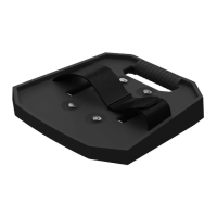
Figure 24:Figure 24: Corner MountingCorner Mounting
– L +– L +
– L +– L +
– R +– R +
– R +– R +
fromfrom
amplifieramplifier
Left 1Left 1
––
++
––
++
––
++
Right 1Right 1
Right 2Right 2Left 2Left 2
11
RR
uu
nn
gg
ss
33
22
 Loading...