13
F INSTALLATION AND ASSEMBLY
F1 Customer responsibilities
The Customer must provide for the following:
- Install a disconnecting switch with a capacity at
least equal to that given in the technical data table,
a 30mA residual current circuit breaker and an
overcurrent device (magnetothermal cut-out with
manual reset or fuse) between the appliance and
the mains power outlet. The chosen device must be
lockable in the open position in case of mainte-
nance.
- install an adequate electrical power supply ahead
of the machine, according to the equipment’s tech-
nical specifications (Table 1 and D2 “Characteris-
tics of power supply”);
- the equipotential connection of the workplace elec-
trical system to the metal structure of the machine
by means of a copper cable of adequate section
(see position “EQ” in par. F6.2 “Installation dia-
grams”);
- Adducting for the electrical connection between the
workplace electric panel and the equipment;
- the water supply and drain connections and other
connections as indicated in Table 1 and par. F6
“Plumbing connections”;
F2 Characteristics of the place of machine
installation
The machine is designed for installation in professional
and not domestic-type kitchens. Water collection traps/
metal grates must be arranged in the floor at the
machine discharges (see pargraph F6.2 “Installation
diagrams”), possibly replaceable with a single water
trap sized for a flow rate of at least 3 l/s.
F3 Machine space limits
A suitable space must be left around the machine (for
operations, maintenance, etc.).
The passages enabling personnel to operate on the
machine must be at least 50 cm wide, except at the
rear of the machine.
The size must be increased in case of use and/or
transfer of other equipment and/or means or if exit
routes are necessary inside the workplace.
F4 Positioning
The machine must be taken to the place of installation
and the packing base removed only when being
installed.
Arranging the machine:
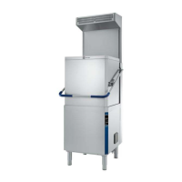
• Wear protective gloves and unpack the machine
(Figure 5).
Figure 5 Unpacking
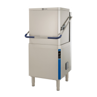
• Lift the appliance using a lift truck, remove the base
and position the appliance where it is to be installed
(
Figure 6).
• Carefully remove the protective film from the outer
panels without tearing it, to avoid leaving traces of
glue (Figure 7).
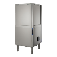
• Adjust the equipment by turning the special adjust-
able feet and making sure it is perfectly level, both
lengthwise and crosswise (Figure 8).
Figure 8 Feet adjustment
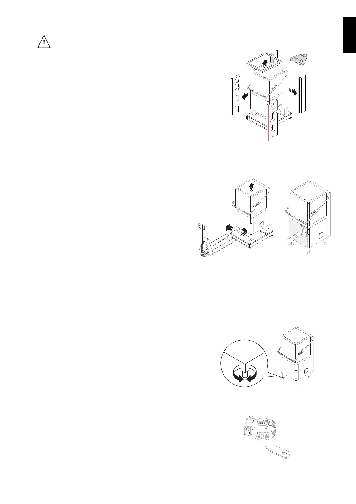
• The appliance must be fixed to the floor using the
two clamps supplied
(Figure 9).
Figure 9 Machine fixing clamp
IMPORTANT!
Machine installation operations must
only be carried out by specialized Techni-
cians provided with all the appropriate
personal protection equipment (safety
shoes, gloves, glasses, overalls, etc.),
tools, utensils and ancillary means.
Figure 6 Machine
positioning
Figure 7 Removing
the film