22
F7 Electrical connections
Connection to the power supply must be carried out in
conformity with the current regulations and provisions
in the country of use.
• Make sure the machine power supply voltage spec-
ified on the rating plate (Table 1) matches the
mains voltage.
• Make sure the system power supply is arranged
and able to take the actual current load and that it is
executed in a workmanlike manner according to the
regulations in force in the country of use.
• The earth wire at the terminal end must be longer
(max. 20 mm) than the phase wires.
• Connect the earth wire of the power supply cable to
an efficient earth clamp. The appliance must also
be included in a unipotential system, the con
-
nection being made through the screw “EQ” (see
pargraph
F6.2 Installation diagrams) marked with
the symbol “ ”. The unipotential wire must have a
cross section of 10 mm
2
.
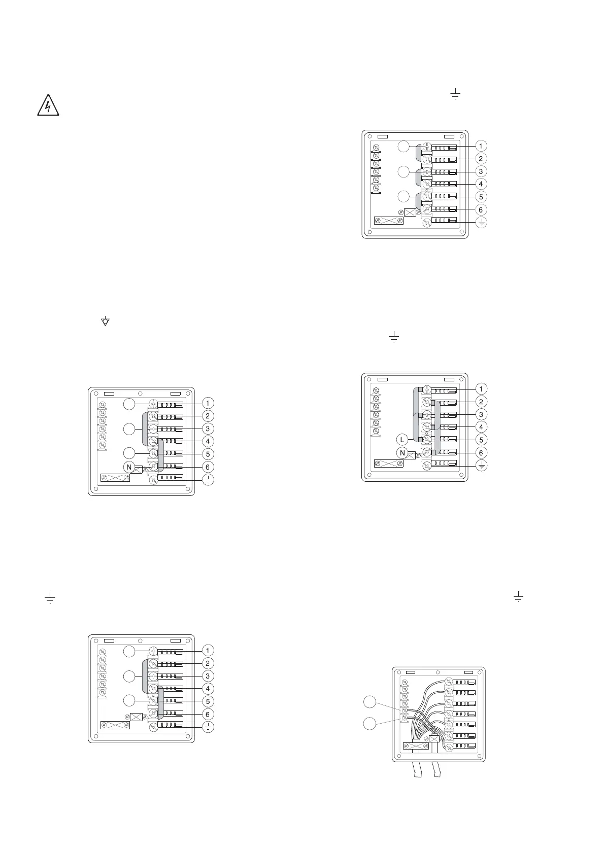
Power supply 380-415V 3N
(standard configuration)
Figure 11 380-415V 3N
Open the power supply terminal board and insert the
jumpers provided as follows: two jumpers between ter-
minals 2 and 4 and two between terminals 4 and 6.
Using a suitable power supply cable (see technical data
table), connect the three phases to terminals 1, 3 and 5,
the neutral to terminal 6 and the earth wire to the termi-
nal .
Power supply 400-440V 3
Figure 12 400-440V 3
Open the power supply terminal board and insert the
jumpers provided as follows: two jumpers between ter-
minals 2 and 4 and two between terminals 4 and 6.
Using a suitable power supply cable (see technical data
table), connect the three phases to terminals 1, 3 and 5
and the earth wire to the terminal .
Power supply 220-240V 3
Figure 13 220-240V 3
Open the power supply terminal board and insert the
jumpers provided as follows: one jumper between termi-
nals 1 and 2, one between terminals 3 and 4 and
another between terminals 5 and 6. Using a suitable
power supply cable (see technical data table), connect
the three phases to terminals 1, 3 and 5 and the earth
wire to the terminal .
Power supply 220-240V 1N
Figure 14 220-240V 1N
Open the power supply terminal board and insert the
jumpers provided as follows: two jumpers between termi-
nals 1 and 3, two jumpers between terminals 2 and 4, one
jumper between terminals 3 and 5 and another two
between terminals 4 and 6.
Using a suitable power supply cable (see technical data
table), connect the phase and neutral to terminals 5 and
6 respectively and the earth wire to the terminal .
F8 Energy control arrangement
The machine is arranged for external control of energy
consumption.
Figure 15 Energy control
IMPORTANT!
Work on the electrical systems must
only be carried out by a qualified electri-
cian.
11
12