EasyManua.ls Logo

Electrolux ERF2600 - Page 10

Electrolux ERF2600
22 pages
Print Icon
To Next Page IconTo Next Page
To Previous Page IconTo Previous Page
Loading...
Q&CI - Technical Support 9 599 83 20-19 Rev. 02
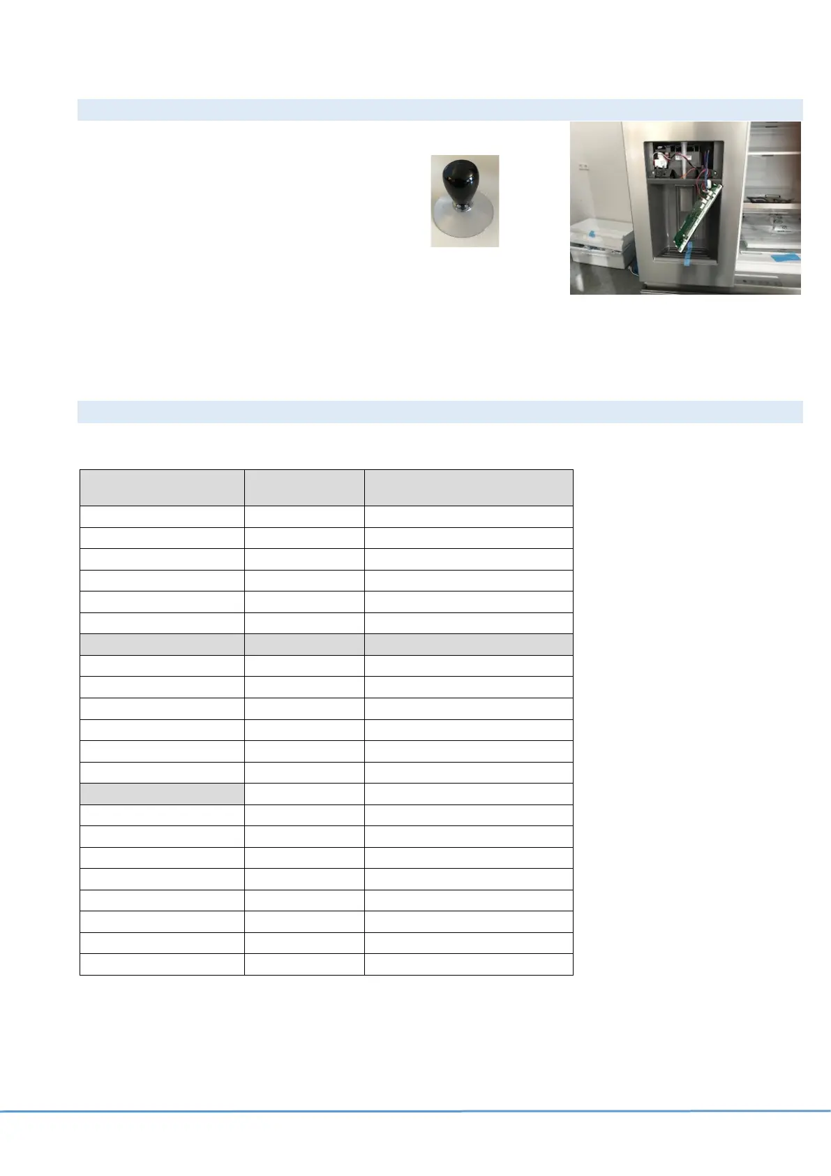
5.2 Disassembly user interface on door
1.
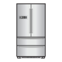
Insert thin plastic tool to clip out the electronic board or use a suction cup.
2.
Disconnect the wire connector.
5.3 Connectors user interface on door PCB
J1 (NIUx INTERFACE) J2 (MACS) J3 (I2C)
1- WiFi RX
1- GND
1-SCL
2-WiFI TX
2- MACS Comm
2-SDA
3-+5V (Controlled)
3- +5V
3-+5V
4-GND
4- +12V
4-GND
5-Not Used
5-Not Used
J4 (DAAS)
JFLASH
J6 (OPTIONAL I/O)
1- DAAS TX
+5V
1- +12V
2- DAAS RX
SWDIO
2- +12V
3- +5V
RESET
3- +12V
4- GND
SWCLK
4- Paddle Sense
GND
5- Flapper Sense
Not Used
6- Dispenser Light
J7 (HEATER)
7- Optional Input
1-+12V
8- Optional Output
2-Heater Output Ohm
9- MC_OUT2 (Flapper motor)
3-+12V
10- MC_OUT1 (Flapper motor)
4-Mid Drawer LED
5-MC_OUT6 (Pump)
6-MC_OUT5 (Pump)
7-MC_OUT4 (Solenoid)
8-MC_OUT3 (Solenoid)

Related product manuals