0408 26
7
D1085
D0463
Notice
Date Page
05102004
INSTALLATION
MANUAL
Evacuation system if several dryers are connected to a common
evacuation duct (except for the gas haeting machines).
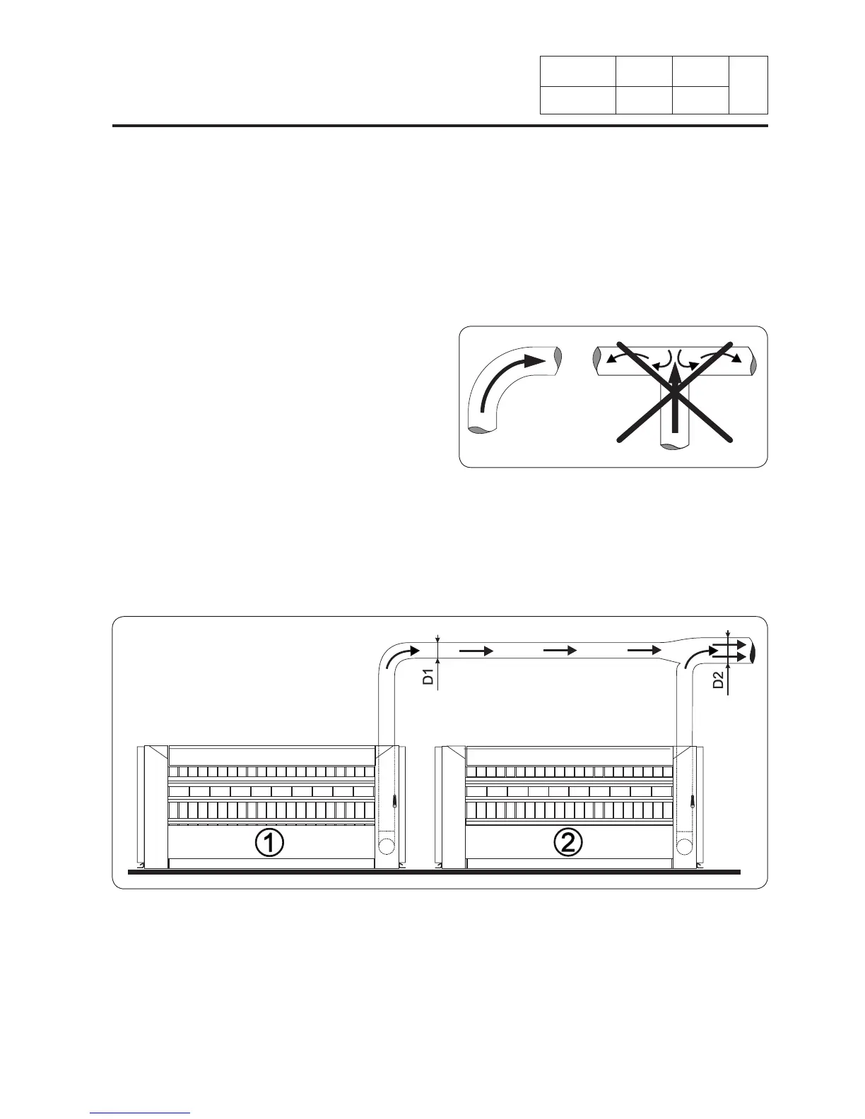
If several dryer ironers are installed with a common evacuation duct, the cross-section of the
evacuation duct must increase as a function of the number of installed machines so that each
of them operates at the same value of air resistance.
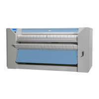
Use elbows (and not Tees) to allow the air to
pass forwards.
The simplied gure below shows the
principle on which the evacuation duct
shape is designed.
Number of ironers
D1 D2 D3 D4
Outlet diameter of the exhaust pipe in (mm) 160 225 315 450
Ventilation aperture required section 2 dm² 4 dm² 8 dm² 16 dm²
The indicated evacuation diameter is the dryer outlet diameter.
Cross-sections of ducts between dryers and the outside of the building must be designed taking
account of the ow and the allowable head loss on each machine and the routing of ducts
(elbows and lengths).
Please call us if you are in any doubt about the layout of your exhaust device if you are
modifying an existing installation.
7. Installation