SOI 01.05 FV 29/33 599 36 78-06
COMPONENT REPLACEMENT AND ADJUSTMENT PROCEDURE
REMOVAL
1. Disconnect the power supply cord.
2. Open the door slightly and remove the built in
frame assembly(Ref: to chapter built in frame
assembly removal).
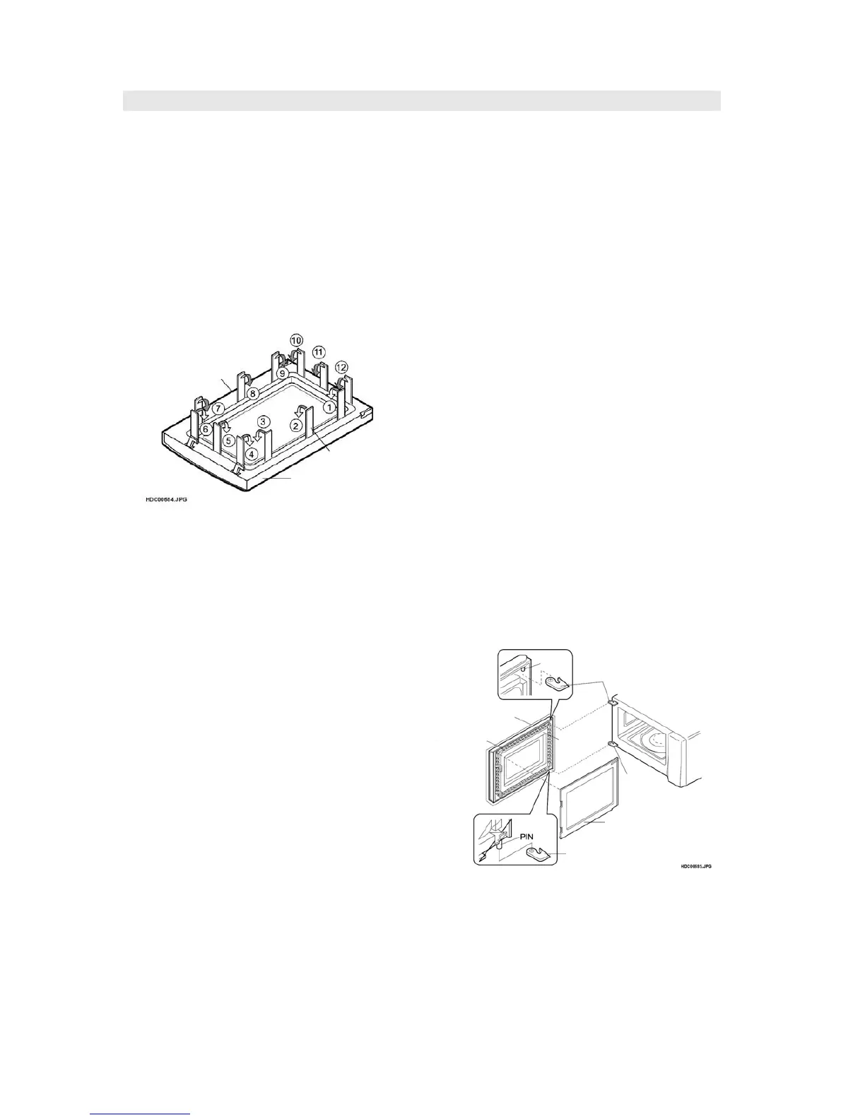
3. Remove the choke cover taking care not to
break clips by inserting an iron plate (thickness
of about 0.5mm) or flat type screw driver to the
gap between the choke cover and door panel
as shown Figure C-4 to free the engaged
parts.
4. Release choke cover from door panel.
5. Now choke cover is free.
Figure C-4. Door Disassembly
6. Release two (2) pins of door panel from two (2)
holes of upper and lower oven hinges by lifting
up.
7. Remove door assy by removing screws (4).
8. Release door panel from tabs of door frame and
remove door frame.
9. Now, door panel with inner sealer film is free.
10.Tear inner sealer film from door panel.
11.Now, door panel is free.
12.Slide latch head upward and remove it from
door frame with releasing latch spring from door
frame and latch head.
13.Now, latch head and latch spring are free.
RE-INSTALL
1. Re-install latch spring to the head. Re-install
latch spring to the door frame. Re-install latch
head to the door frame.
2. Re-install door panel to door frame by fitting tabs
of door frame to holes of door panel.
3. Put sealer film on door panel. Refer to “Inner
Sealer Film” and figure C-6, on how to handle
the new film.
4. Catch two (2) pins of door panel on two (2) hole
of upper and lower oven hinges.
5. Re-install choke cover to door panel by pushing.
Note: After any service to the door;
(A) Make sure that monitored latch switch, stop
switch and monitor switch are operating
properly. (Refer to chapter “Test
Procedures , Switch Test page 17”.).
(B) An approved microwave survey meter
should be used to assure compliance with
proper microwave radiation emission
limitation standards.
After any service, make sure of the following :
1. Door latch heads smoothly catch latch hook
through latch holes and that latch head goes
through center of latch hole.
2. Deviation of door alignment from horizontal line
of cavity face plate is to be less than 1.0mm.
3. Door is positioned with its face pressed toward
cavity face plate.
4. Check for microwave leakage around door with
an approved microwave survey meter. (Refer to
Microwave Measurement Procedure.)
Note: The door on a microwave oven is
designed to act as an electronic seal
preventing the leakage of microwave
energy from oven cavity during
cook cycle. This function does not require
the door be air-tight, moisture
(condensation)-tight or light-tight.
Therefore, occasional appearance
of moisture, light or sensing of gentle
warm air movement around oven door is
not abnormal and does not indicate
leakage of microwave energy from the
oven cavity.
Figure C-5. Door Replacement
NOTE: When carrying out any repair to the
door, do not bend or warp the slit
choke (tabs on the door panel
assembly) to prevent microwave
leakage.
Choke Cover
Putty Knife
Door Frame
PIN
UPPER
OVEN HINGE
DOOR SUB
ASSEMBLY
DOOR
PANEL
SLIT CHOCHE
CHOKE COVER
LOWER
OVEN
HINGE
LOWER
OVEN HINGE