36
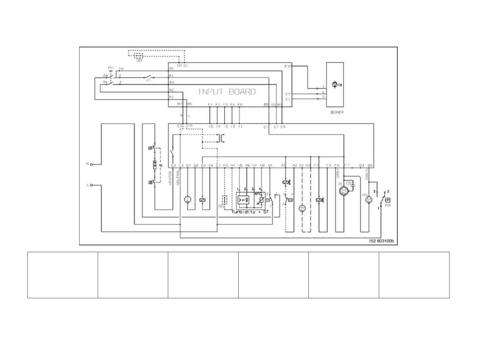
11 BASIC CIRCUIT DIAGRAM
AR = Orange
BI = White
BL = Blue
CE = Light blue
GI-VE = Yellow-green
MA = Brown
NE = Black
RO = Pink
VI = Violet
AA/DA = Anti-flooding device
CO = Capacitor
DD = Detergent/rinse-aid
dispenser
EC = Fill solenoid
ER = Regeneration solenoid
GA = Interference filter
IP = Door switch
MR = Terminal block
MV = Fan motor
PL = Wash pump
PS = Drain pump
PU = Button array
PR/RL = Level pressure switch
PA = Anti-overflow level switch
RR = Heating element
SB = Rinse-aid sensor
SS = Salt sensor
Turbidity = Turbidity sensor
ST = Temperature sensor
TAC/T = Tachometric generator
TS = Safety thermostat
Main Board = Main circuit board
User Interface = Display board