Installation Instructions
10
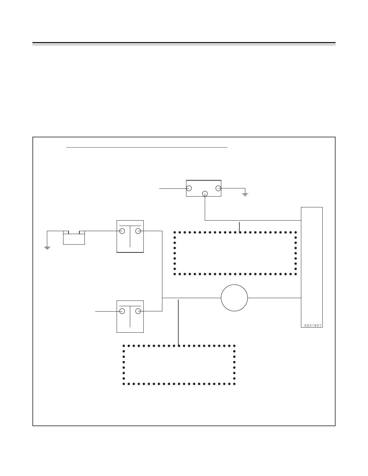
Batt.
Master Switch
Contactor
Alternator
F
B
G
Starter Solenoid
VA-1A or External Shunt
+
-
This line may be connected currently
to the Master Switch Contactor or
the Starter Solenoid. In that case it
should be rerouted to the Bus or +
side of the Shunt.
B
U
S
This is the main lead going to the
Bus. It may come from the Master
Switch Contactor or the Starter
Solenoid.
To Starter
To Voltage Regulator
Figure 1: VA-1A or External Shunt Installed in the Battery Lead
Note: The VA-1A or External Shunt should not be installed in series with the starting current.
With the improvements made to the VA-1A there are few disadvantages using either method.
Although EI’s test pilot has a slight preference for the alternator lead when using the VA-1A, ease
of installation should be the determining factor. In most cases installing the VA-1A is a simple
matter of replacing your existing unit and adding a few wires (see Wiring Diagram).
Following is a typical diagram of each installation. Determine how the VA-1A or External Shunt
will be installed in your aircraft.
3. Determine how the VA Unit will be installed